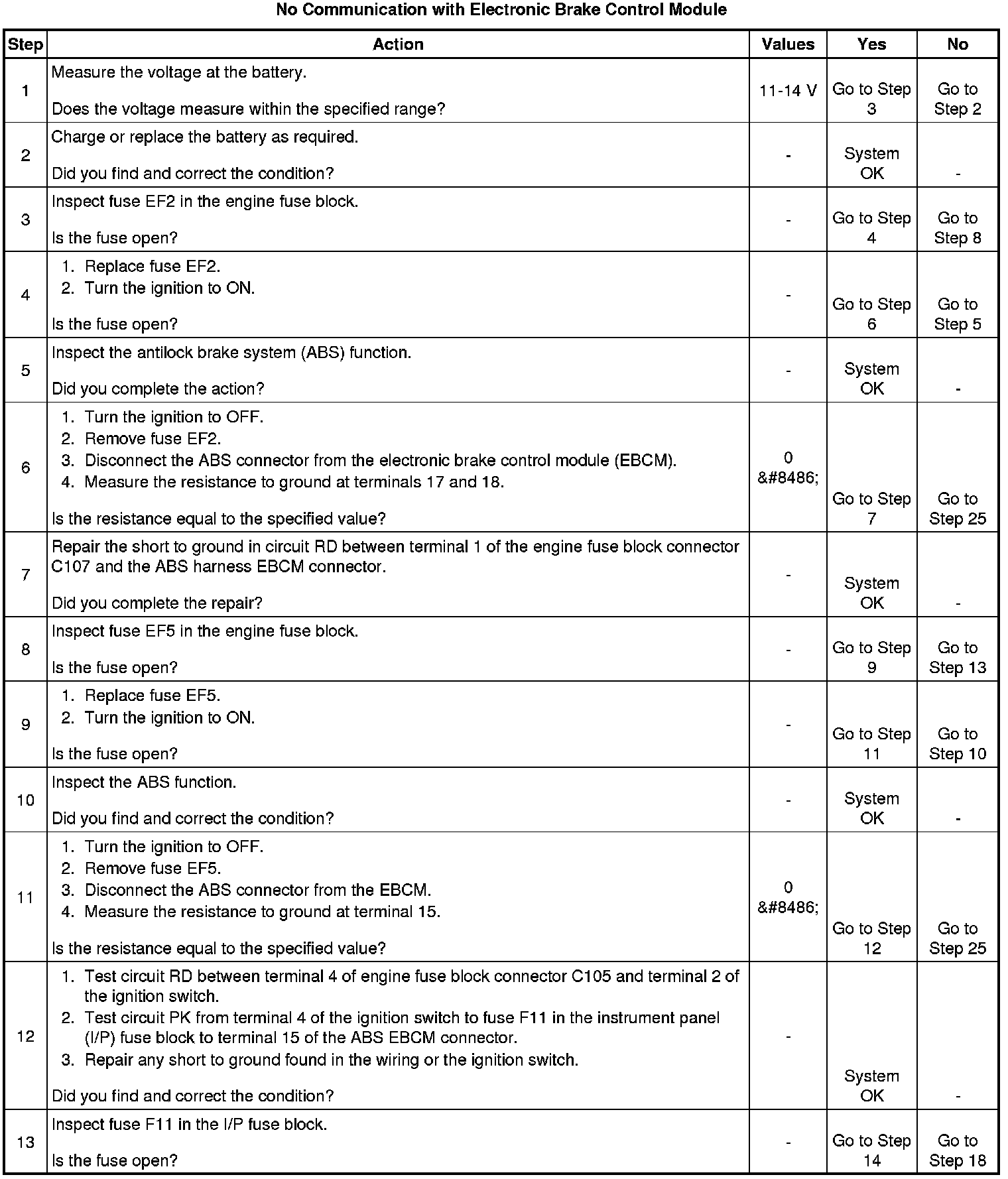
No Communication with Electronic Brake Control Module
No Communication with Electronic Brake Control Module
Circuit Description
Battery voltage is supplied to the electronic brake control module (EBCM) through fuse F11 in the instrument panel (I/P) fuse block, to terminal 15 of the EBCM connector. The voltage is present when the ignition switch is in the ON or START position.
This test checks for battery output, proper grounding, blown fuses, a faulty ignition switch, and problems in the circuitry.
Conditions for Setting the DTC
* The battery is defective.
* There is a defective ground connection.
* A connector is damaged.
* A wire is broken or shorted.
* A fuse is blown.
* The ignition switch is malfunctioning.
Action Taken When the DTC Sets
The antilock brake system (ABS) action is disabled during the period of low voltage.
Diagnostic Aids
It is very important to perform a thorough inspection of the wiring and the connectors. Failure to do so may result in misdiagnosis, causing part replacement with a reappearance of the malfunction.
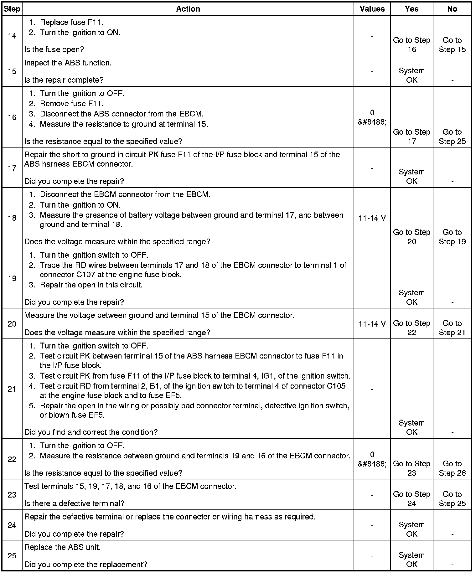
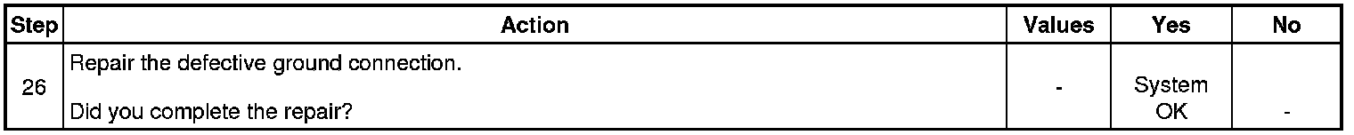
Test Description
The numbers below refer to the step numbers on the diagnostic table.
1.
This step determines whether there is voltage at the battery and the high current source.
7.
This step inspects for voltage at the ignition 1 source.
11.
This step begins the check for voltage at the EBCM end of the ABS harness.
15.
This step inspects for a defective ground connection.
16.
This is an inspection for a defective EBCM connector.