Disassembly
Fig. 2 Exploded view of Rochester M4MC Quadrajet carburetor (Part 1 of 2):

Fig. 2 Exploded view of Rochester M4MC Quadrajet carburetor (Part 2 of 2):

Fig. 3 Exploded view of Rochester M4ME Quadrajet carburetor (Part 1 of 2):

Fig. 3 Exploded view of Rochester M4ME Quadrajet carburetor (Part 2 of 2):

Fig. 4 Exploded view of Rochester M4MED Quadrajet carburetor (Part 1 of 2):

Fig. 4 Exploded view of Rochester M4MED Quadrajet carburetor (Part 2 of 2):
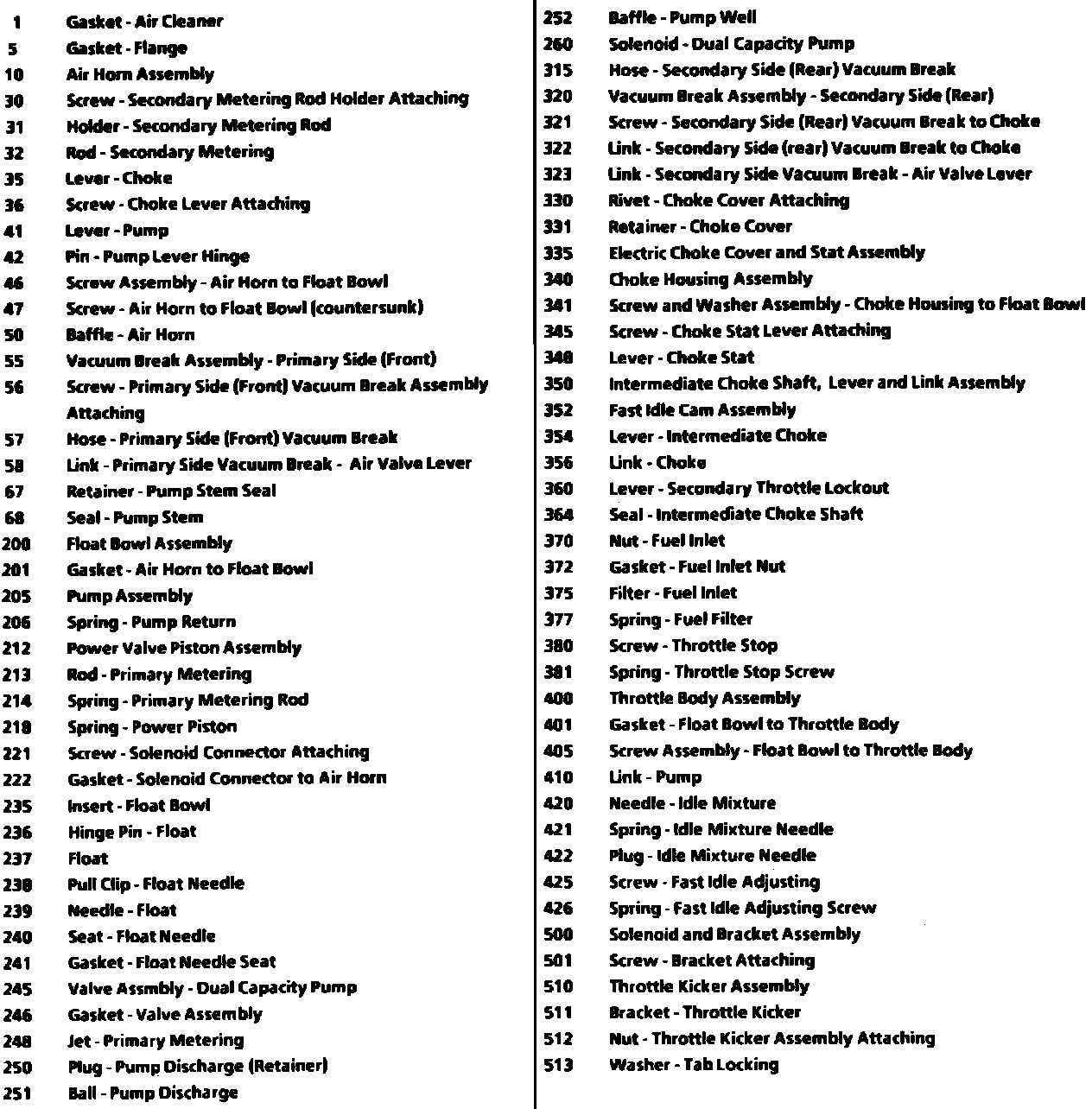
Fig. 5 Exploded view of Rochester M4MEF Quadrajet carburetor (Part 1 of 2):
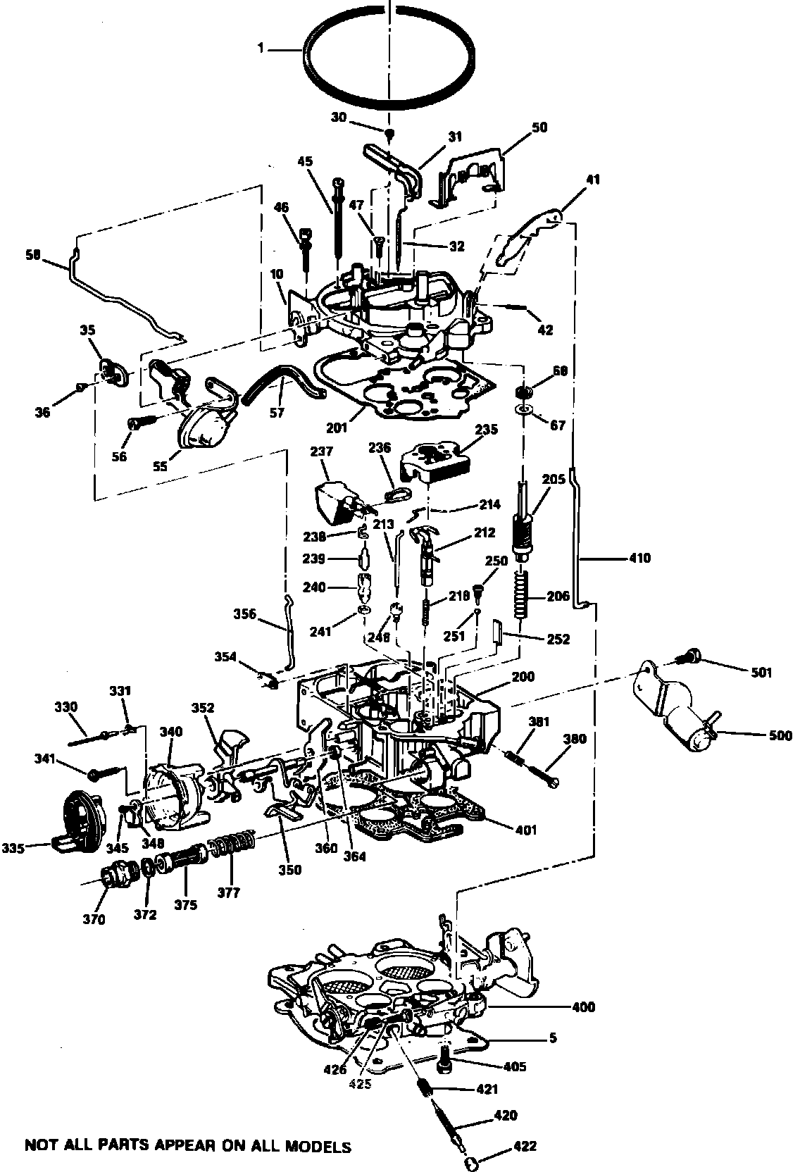
Fig. 5 Exploded view of Rochester M4MEF Quadrajet carburetor (Part 2 of 2):

Refer to Figs. 2 through 5, when performing procedures on these carburetors.
1. Remove idle speed solenoid or throttle kicker assembly.
2. Disconnect front vacuum break hose, if equipped, then remove vacuum break assembly attaching screws, vacuum break assembly and air valve lever link.
3. Disconnect rear vacuum brake hose, if equipped, then remove attaching screws. Rotate vacuum brake assembly to disconnect link from slot, then remove vacuum brake assembly. Remove vacuum brake air valve lever link, then the vacuum break to choke link.
4. Support carburetor in a suitable holding fixture. Remove choke cover retaining screws, then the retainers, choke cover and gasket, if used. If equipped with tamper resistant choke cover, drill rivet heads from rivets with a 5/32 inch drill bit. Drive rivets from choke housing using a suitable drift, then remove retainers, choke cover and gasket, if used.
5. Remove fuel inlet nut, filter, gasket and spring, then the idle mixture needle plugs.
6. Remove choke lever attaching screw, then the choke lever. Holding intermediate choke lever outward, twist and remove choke link from lever.
7. Remove secondary metering rod holder attaching screw, then the rod holder and secondary metering rods.
8. Using a suitable punch, drive pump lever hinge pin in slightly to permit lever to be removed from between bosses on air horn. Disconnect pump lever from rod, noting position of rod in lever.
9. Remove air horn attaching screws, then the secondary air horn baffle, if used. Lift air horn upward and remove from float bowl. Use caution to prevent damaging the small tubes pressed into the air horn casting. Do not remove tubes from casting.
10. If pump plunger stem seal is used, invert air horn and remove staking holding seal retainer in place. Remove and discard retainer and seal.
11. For cleaning purposes, the air horn does not require further disassembly. If air horn valve closing spring or plastic cam requires replacement, follow procedures outlined in repair kit. On model M4MEF carburetors, do not turn or try to remove the rich stop adjusting bushing since damage to engine or increased exhaust emissions will result.
12. Remove air horn to float bowl gasket and discard. On M4MED carburetors, disconnect solenoid connector before removing gasket.
13. Remove accelerator pump return spring.
14. Remove power valve piston and metering rod assembly by pushing downward on piston stem, then releasing until piston snaps upward against retainer. Remove power piston spring from bore. Do not attempt to change the factory setting of the A.P.T. metering rod adjusting screw located in bore next to power piston bore. Adjustment of this screw could result in increased exhaust emissions. If float bowl requires replacement, then new float bowl will contain a pre-set A.P.T adjusting screw.
15. Note position of metering rod tension springs, then disconnect springs from each metering rod. Rotate metering rods and remove from power piston assembly.
16. Remove float bowl insert, float needle, float seat seat and gasket, using a suitable tool. Remove aneroid cavity insert, if equipped.
17. On M4MED models carburetors, remove dual capacity pump solenoid and valve assemblies.
18. On all models, remove primary metering jets. Do not attempt to remove secondary metering jets. If jets are damaged, replacement of entire float bowl is required.
19. Remove accelerator pump discharge check ball retainer, then invert float bowl and remove check ball. Remove pump well baffle.
20. Remove choke housing retaining screw and washer, then the choke housing assembly. If applicable, remove housing to float bowl seal.
21. Remove secondary throttle valve lockout lever, then the intermediate choke lever.
22. Remove choke coil lever attaching screw, then the choke coil lever.
23. Remove intermediate choke shaft, lever and link assembly, then the fast idle cam. Remove intermediate choke shaft seal, if applicable.
24. For cleaning purposes, no further disassembly of the float bowl is required. Do not remove secondary well bleed screw plug or screw, if equipped. Unnecessary adjustment of screw could result in engine damage or increased exhaust emissions.
25. Remove float bowl to throttle body attaching screws, then separate throttle body from float bowl and remove gasket.
26. Remove accelerator pump link from throttle lever.
27. No further disassembly of throttle body is required. If necessary, remove idle mixture needles from throttle body, counting number of turns necessary to seat needles.