With 4L80-E Transmission
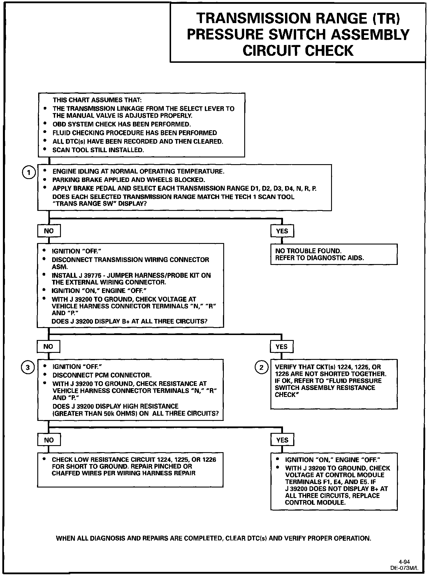
Transmission Range (TR) Pressure Switch Chart:
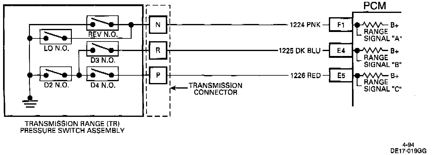
Transmission Range Pressure Switch Circuit:
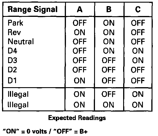
Range Combinations:
CIRCUIT DESCRIPTION
The Transmission Range (TR) switch assembly consists of five pressure switches (two normally closed and three normally open), and a Transmission Fluid Temperature (TFT) sensor combined into one unit and mounted on the valve body.
The Powertrain Control Module (PCM) supplies battery voltage to each range signal. By grounding one or more of these circuits through various combinations of the pressure switches, the PCM detects what manual valve position has been selected by the vehicle operator. With ignition "ON" and engine "OFF," Park/Neutral (P/N) will be indicated.
When the transmission electrical connector is disconnected, the ground potential for the three range signals to the PCM will be removed, and with ignition "ON," D2 will be indicated.
DIAGNOSTIC TROUBLE CODE (DTC) CHART TEST DESCRIPTION
Number(s) below refer to circled number(s) on the diagnostic charts:
1. This test checks the indicated range signal to the manual valve position actually selected.
2. This test checks for correct voltage from the PCM to the transmission external connector.
3. This test checks for a short to ground from the PCM to the transmission external connector in any one of the three circuits.
DIAGNOSTIC AIDS
Refer to image #3 for various A/B/C range combinations. Check all wiring connectors for proper terminal tension. Perform a resistance check on the transmission range switch if necessary.