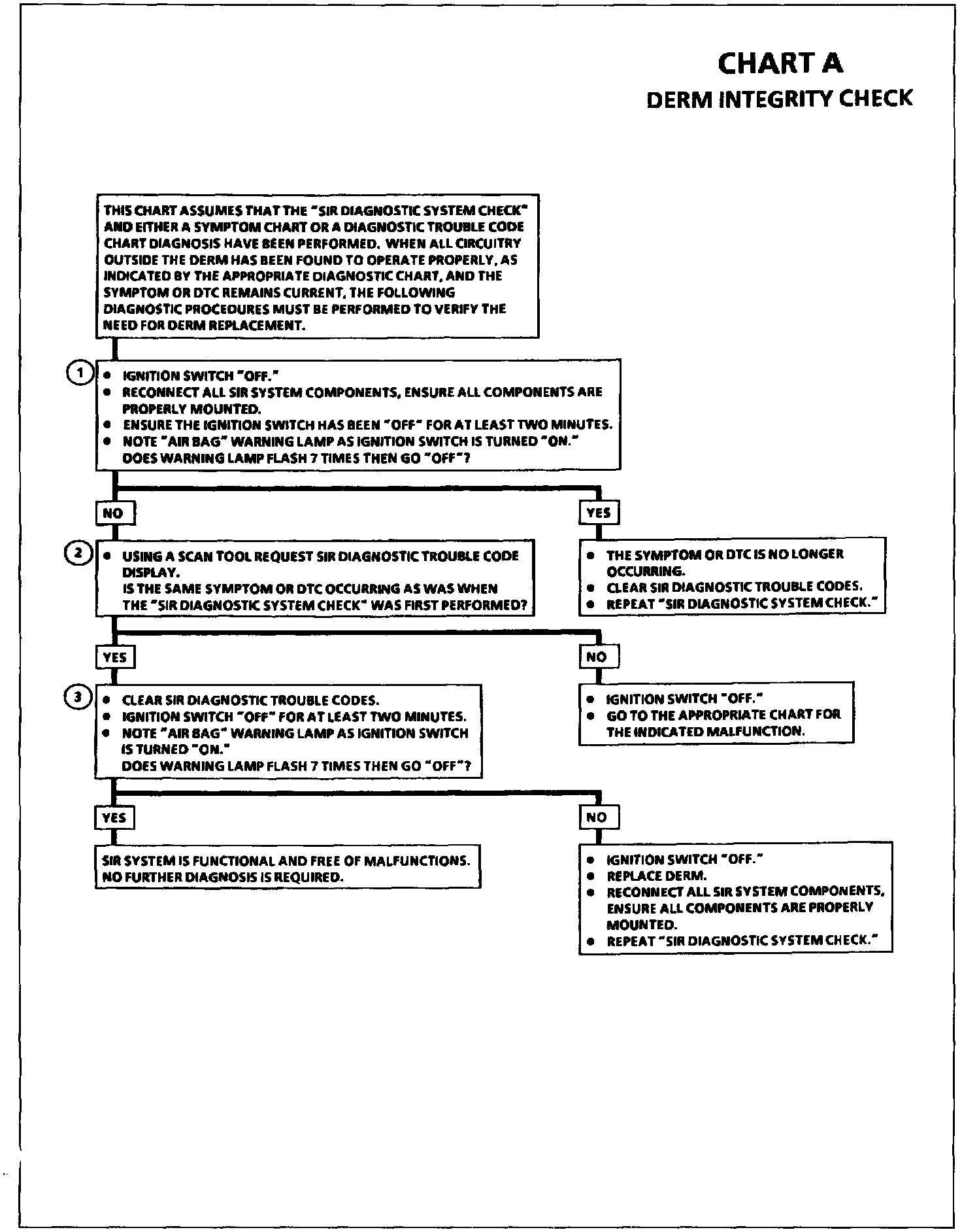
Chart A SDM Integrity Check
Wiring Diagram:
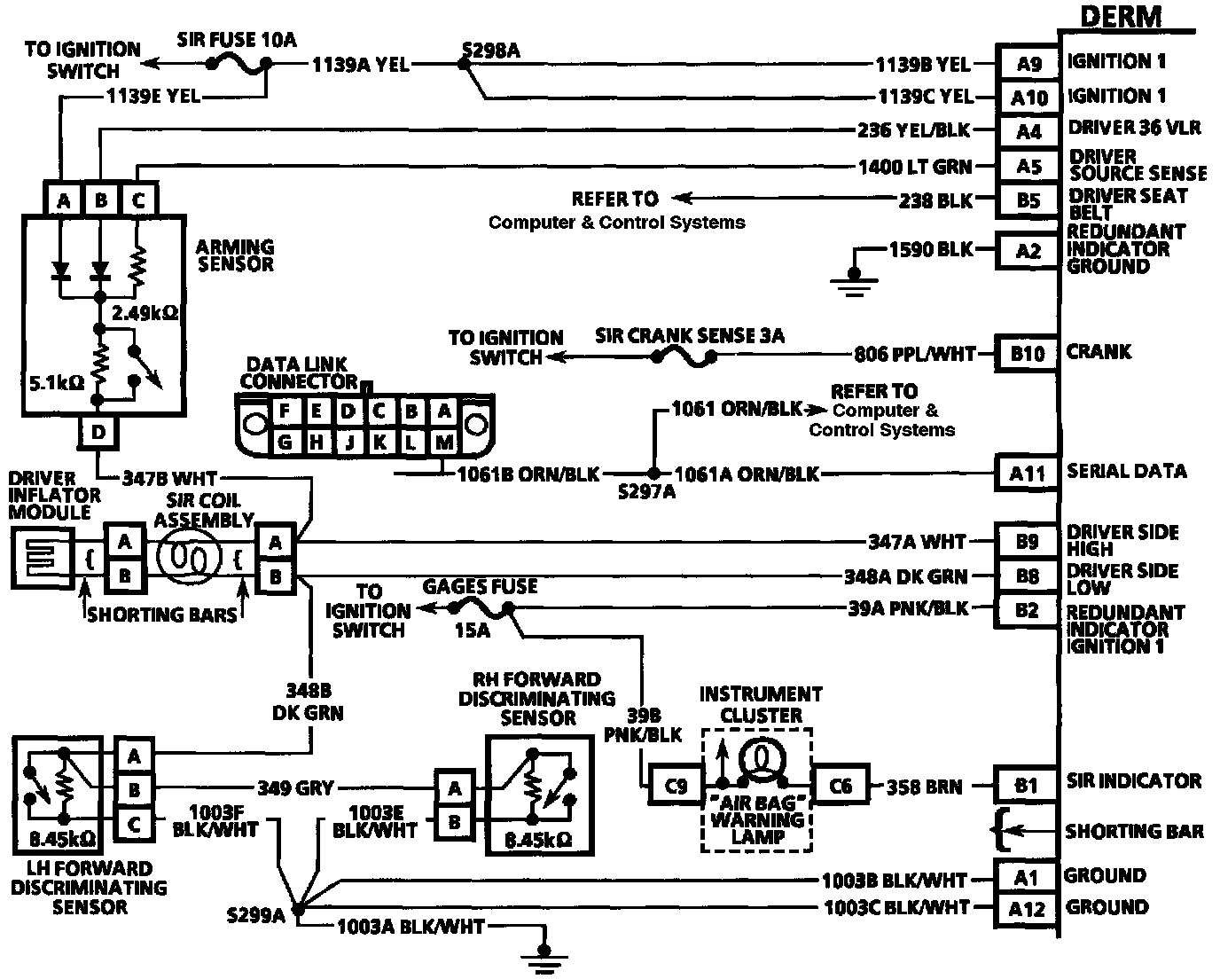
CIRCUIT DESCRIPTION
When the DERM recognizes "Ignition 1" voltage, applied to terminals "A9" and "A10," is in the normal operating voltage range, the "AIR BAG" warning lamp is flashed 7 times to verify operation. At this time the DERM performs "Turn-ON" tests followed by "Continuous Monitoring" tests. When no malfunctions are detected the DERM proceeds to the "Initiator Assembly Resistance Test." When a malfunction is detected the DERM sets a current diagnostic trouble code and illuminates the "AIR BAG" warning lamp. The DERM will clear current diagnostic trouble codes and move them to a history file when the malfunction is no longer detected and/or the ignition switch is cycled, except for DTC 51. DTC 51 can only be cleared using a scan tool "Clear Codes" command.
CHART TEST DESCRIPTION
Number(s) below refer to circled number(s) on the diagnostic chart.
1. This test confirms a current malfunction. If no current malfunction is occurring (History DTC set) the "Diagnostic Aids" for the appropriate diagnostic trouble code should be referenced. The DERM should not be replaced for a history diagnostic trouble code.
2. This test checks for a malfunction introduced into the SIR system during the diagnostic process. It is extremely unlikely that a malfunctioning DERM would cause a new malfunction to occur during the diagnostic process.
3. When all circuitry outside the DERM has been found to operate properly, as indicated by the appropriate diagnostic table, then and only then should the DERM be replaced.