Solid State Symbols
A group of special symbols is used to represent electronic circuits used in solid state modules. These symbols are greatly simplified versions of the actual circuits. They can be very useful for troubleshooting purposes if properly used. It is important to remember that these symbols apply only to modules with all connectors in place and supply voltages ON.Solid State Switch:
Solid State Switch:
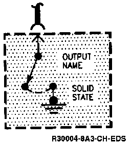
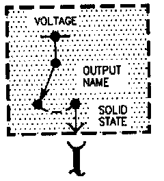
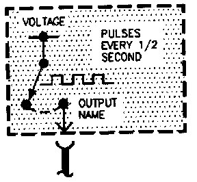
Outputs
The Solid State Switch is used to turn ON a circuit outside the module. When the switch closes, the voltage or ground shown will be applied to the connected circuit. Additional information about what makes the switch close is often provided. The voltage controlled by the switch may be measured just as if it were a mechanical switch.
Symbols:
Symbols:
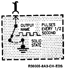
These symbols are similar to the Solid State Switch. The pulses represent the rate at which the switch is turned ON and OFF.
Symbols:
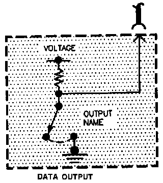
Symbols:
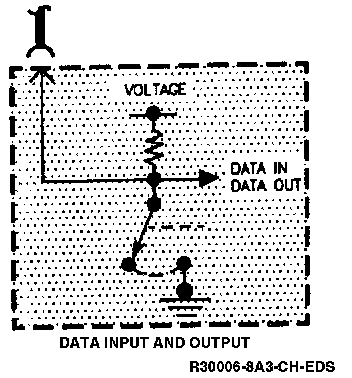
These two symbols are special versions of the Solid State Switch. They represent serial data inputs and outputs. Serial data consists of coded groups of voltage pulses transmitted at HI speed. These pulses cannot usually be measured with a Digital Voltmeter. There are cases however where procedures in System Diagnosis may describe such measurements. A Scan tool can often read and display this data.
Symbols:
Symbols:
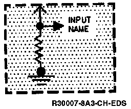
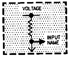
Inputs
These Symbols represent the equivalent circuit at the input terminals of electronic modules. You should not attempt to measure the resistance of these terminals unless instructed to do so by a service procedure. These inputs can be used to check wiring to electronic modules (refer to General Troubleshooting Procedures). Diagnostic Aids