Four-Step Troubleshooting Procedure
STEP 1: CHECK THE PROBLEMPerform a System Check to be sure you understand what's wrong. Don't waste time fixing part of the problem! Do not begin disassembly or testing until you have narrowed down the possible causes.
If the system you are troubleshooting has a built-in self- diagnostic system, enter diagnostics and check for trouble codes.
STEP 2: READ THE ELECTRICAL SCHEMATIC
Study the schematic. Read the Circuit Operation text if you do not understand how the circuit should work. Check circuits that share wiring with the problem circuit. The names of circuits that share the same fuse, ground, switch, etc. are included on each electrical schematic. (Shared circuits are also shown on Power Distribution, Ground Distribution and I/P Fuse Block/Relay Center Details.) Try to operate the shared circuits. If these circuits work, then the shared wiring is OK. The cause must be within the wiring used only by the problem circuit. If several circuits fail at the same time, chances are the power (fuse) or ground circuit is faulty.
STEP 3: FIND THE CAUSE AND REPAIR
^ Narrow down the possible causes.
^ Use the Troubleshooting Hints.
^ Make the necessary measurements as given in the System Diagnosis.
Before you replace a component, check power, signal, and ground wires at the component harness connector. If these are OK, the component must be bad.
STEP 4: TEST THE REPAIR
Repeat the System Check to be sure you have fixed the whole problem.
EXAMPLE: A customer brings in a vehicle and says that the HI beams do not work.
Step 1: Perform System Check on the Headlamps Circuit. You may discover that both LO beams operate. In HI, you may notice that the HI Beam Indicator comes "ON", but neither beam operates.
Typical Headlamp Schematic:
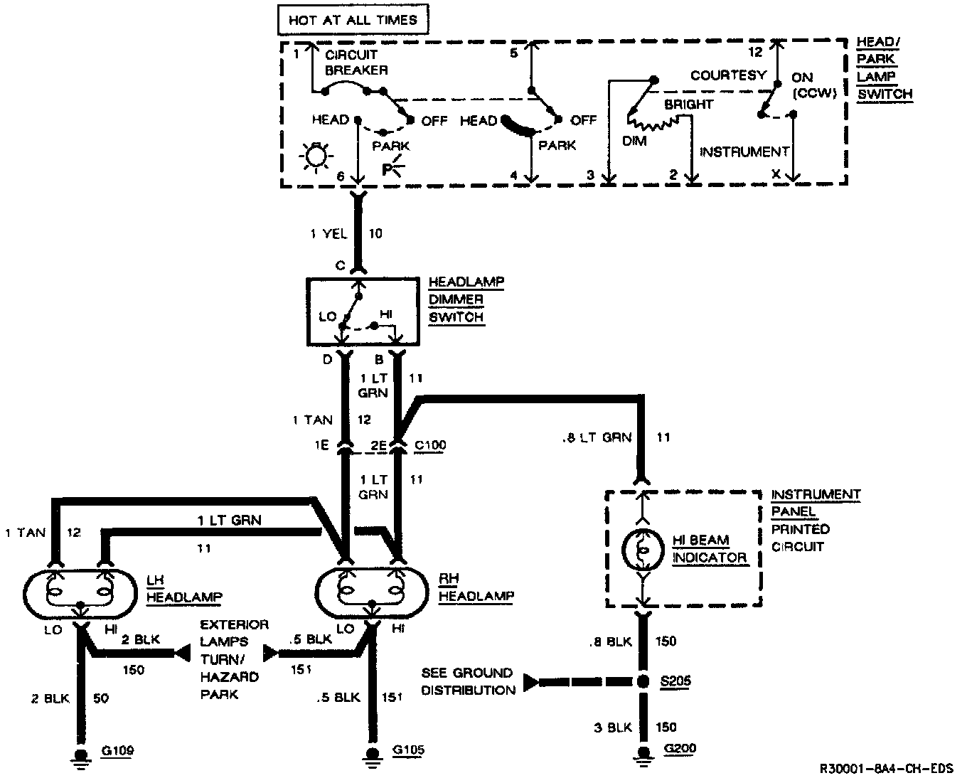
Step 2: Read the Headlamps electrical schematic. This is the step that will save you time and labor. Remember, it is essential to understand how a circuit should work before trying to figure out why it doesn't.
After you understand how the circuit should operate, read the schematic again. This time keeping in mind what you have learned by operating the circuit.
Since both LO beams work, you know that the Head/Park Lamp Switch, the YEL wire, the LO contacts of the Headlamp Dimmer Switch, terminal 1E of C100, the TAN wires, and grounds G105 and G109 are all good.
Furthermore, since you saw that the HI Beam Indicator came "ON" when the Headlamp Dimmer Switch was moved to HI, you know that the HI contacts of the dimmer switch and the LT GRN wire between the dimmer switch and C100 are good.
At this point, you could test for voltage at the RH Headlamp with the dimmer switch in HI. However, it is extremely unlikely that the HI beam filaments have burned out in both headlamps or that both headlamp connections are bad. The cause must be a bad connection at C100, or a break in the LT GRN wire between C100 and the RH Headlamp.
You have quickly narrowed the possible causes down to one specific area and have done absolutely no work on the vehicle itself.
Step 3: Find the cause and repair it. Using the Component Location List and the corresponding figure, you can quickly find C100 and the LT GRN wire, locate the exact trouble point, and make the repair.
Step 4: Check the repair by performing a system check on the Headlamps circuit. This, of course, means making sure that both HI beams, both LO beams and the HI Beam Indicator are all working.
Now suppose that the symptoms were different. You may have operated the Headlamps and found that the LO beams were working, but neither the HI beams nor the HI Beam Indicator was working. Looking at the schematic, you might conclude that is unlikely that both HI beam filaments and the HI Beam Indicator have all burned out at once. The cause is probably the dimmer switch or its connector.