Final Assembly and Adjustment
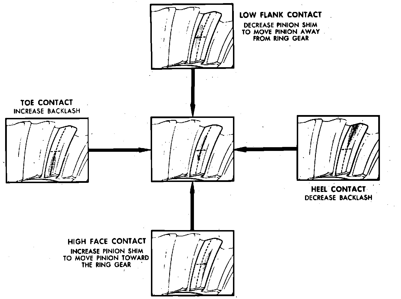
Fig. 19 Gear tooth contact inspection:
1. Ensure that pinion depth and bearing preload are properly adjusted.
2. Install differential case assembly and selected side bearing shims. Refer to Side Bearing Preload & Backlash. Side Bearing Preload & Backlash
3. Install bearing caps in proper position and torque cap bolts to 55 ft. lbs.
4. Rotate assembly to ensure that bearings are properly seated.
5. Mount dial indicator on housing with plunger bearing against tooth on ring gear, Fig. 18. Use small contact button on indicator plunger so that contact can be made at heel end of tooth and position dial indicator with plunger in line with gear rotation and perpendicular to gear tooth.
6. Hold pinion stationary and rock ring gear back and forth while reading backlash on indicator.
7. Check backlash at 3 evenly spaced positions around ring gear and record readings. If backlash varies by more than .002 inch at any position, check ring gear installation and runout, and correct as needed.
8. If backlash is not within specifications, remove differential case assembly and bearing shims keeping shims in order. If ring gear and pinion are being reused, backlash should be adjusted as close as possible to value measured prior to disassembly.
9. Backlash is adjusted by increasing thickness of one shim while decreasing thickness of opposite side shim by the same amount in order to maintain proper side bearing preload. Select shims to adjust backlash as follows:
a. If backlash is excessive, decrease thickness of shim on gear tooth side and increase thickness of shim on opposite side by the same amount.
b. If backlash is less than specified, increase thickness of shim on gear tooth side while decreasing thickness of opposite shim by the same amount. On models with 7-1/2 & 7-5/8 inch ring gear, each .002 inch change in shim thickness alters backlash by .001 inch. On models with 8-1/2 and 8-5/8 inch ring gear, each .003 inch change in shim thickness alters backlash by .002 inch.
10. Reinstall differential assembly, shims and bearing caps, torque bearing cap bolts to 55 ft. lbs., then recheck backlash and adjust as needed.
11. If side bearing preload was set to zero during side bearing preload adjustment, proceed as follows:
a. Remove both bearing caps and shim packs, keeping shim packs in respective left or right positions.
b. Select shim .004 inch thicker than one removed from left side, insert shim between left bearing race and spacer, then install left bearing cap with bolts hand tight.
c. Select shim .004 inch thicker than one removed from right side and install shim between right bearing race and spacer using suitable driver.
d. Install right bearing cap and torque all cap bolts to 55 ft. lbs.
12. Ensure that ring gear teeth are clean and free from oil, then coat both drive and coast side of each tooth with suitable marking compound.
13. Apply braking force to ``load'' ring gear, then rotate driveshaft yoke with wrench so that ring gear rotates one full revolution in each direction. Test made without ``loading'' gears will not yield satisfactory pattern, and excessive rotating of gears is not recommended.
14. Compare gear tooth pattern with Fig. 19, and correct assembly adjustments as needed.
15. When proper gear tooth contact pattern has been obtained, clean marking compound from gears, install cover and new gasket and fill housing with specified lubricant.