Part 1
Engine Replacement 1 - 64
Tools Required
* J 24319-B Steering Linkage and Tie Rod Puller
* J 45341 Rear Wheel Drive Shaft Removal Tool
* J-2619-A Slide Hammer
* J 44394 Axle Seal Protector
* J 45059 Angle Meter
Removal Procedure

1. Raise the hood.
2. Disconnect the negative battery cable.
3. Remove the air cleaner assembly.
4. Relieve the fuel system pressure.
5. Disconnect the fuel feed line from the fuel rail.

6. Disconnect the evaporative emission (EVAP) line from the EVAP purge solenoid.
7. Remove the windshield washer solvent reservoir.
8. Drain the cooling system.
9. Remove the engine drive belt.
10. Remove the left side engine splash shield.
11. Remove the catalytic converter.

12. Disconnect the cooling fan electrical connector.
13. Lower the vehicle.

14. Remove the engine control module (ECM)/transaxle control module (TCM) cover.

15. Disconnect the body harness electrical connector (1) from the ECM.

16. Disconnect the engine harness electrical connector (2) from the ECM.

17. Open the junction block terminal cover.
18. Remove the junction block terminal nut (1).
19. Remove the positive/negative battery cable terminal (2) from the stud.
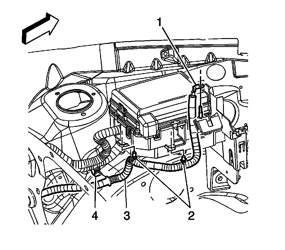
20. Remove the positive battery cable terminal (1) from the junction block stud.
21. Reposition the engine harness as necessary to access the ECM bracket lower bolts.

22. Remove the ECM bracket nuts (1) and bolts (2).
23. Lift the ECM bracket off of the studs and secure the bracket out of the way.

24. Reposition the radiator inlet hose clamp at the engine.
25. Remove the radiator inlet hose from the engine.

26. Disconnect the evaporative emission (EVAP) purge solenoid electrical connector (1).

27. Remove the engine harness clip (1) from the EVAP purge solenoid bracket.

28. Reposition the radiator outlet hose clamp at the engine.
29. Remove the radiator outlet hose from the engine.

30. Reposition the heater inlet and outlet hose clamps at the thermostat housing.
31. Remove the heater inlet and outlet hoses from the thermostat housing.

32. Disconnect the engine coolant heater cord, if necessary.

33. If the vehicle is equipped with a manual transaxle, remove the engine coolant heater cord clips (1) from the camshaft cover, if equipped.
34. If the vehicle is equipped with a automatic transaxle, remove the engine coolant heater cord straps from the engine harness, if equipped.
35. Reposition the engine coolant heater cord out of the way, if necessary.

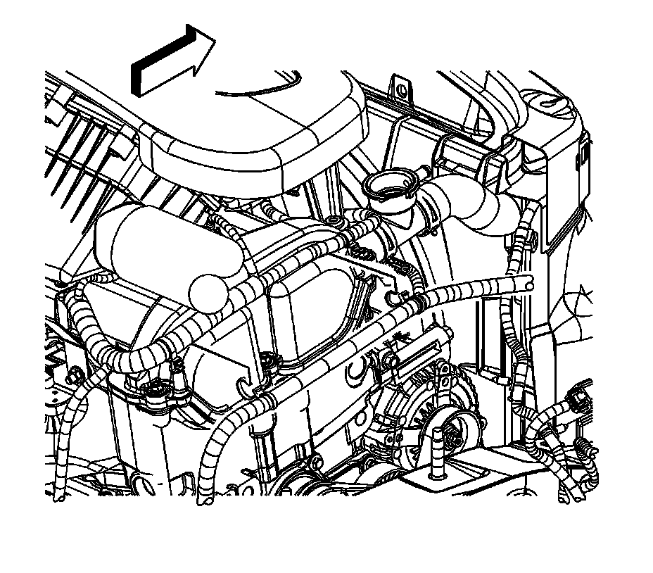
36. Reposition the brake booster vacuum hose clamp at the engine.
37. Remove the brake booster vacuum hose.

38. Disconnect the following electrical connectors:
* Throttle actuator control (TAC) (1)
* Manifold absolute pressure (MAP) sensor
* Fuel injector harness (2)
* Generator (3)

39. Disconnect the ignition control module electrical connector.

40. If equipped with a manual transaxle perform the following steps, remove the engine harness clip (1) from the oil level indicator tube bracket.
41. Remove the engine harness clips (2, 4) from the intake manifold.

42. If equipped with a automatic transaxle perform the following steps, remove the engine harness clip (1) from the oil level indicator tube bracket.
43. Remove the engine harness clips (3, 5) from the intake manifold.

44. Remove the starter.
45. If equipped with a automatic transaxle perform the following steps, remove the positive/negative battery cable ground nut (1).
46. Remove the positive/negative cable (2) terminal from the stud.
47. Remove the engine harness ground terminal (3) from the stud.
48. Disconnect the following electrical connectors:
* Crankshaft position (CKP) sensor (4)
* Oil pressure sensor (5)
* Knock sensor (6)

49. If equipped with a manual transaxle perform the following steps, remove the positive/negative battery cable ground nut (2).
50. Remove the positive/negative cable (3) terminal from the stud.
51. Remove the engine harness ground terminal (4) from the stud.
52. Disconnect the following electrical connectors:
* Crankshaft position (CKP) sensor (1)
* Oil pressure sensor (5)
* Knock sensor (6)

53. If the vehicle is equipped with a manual transaxle, remove the engine harness clip nut (2).
54. Remove the engine harness clip (1) from the transaxle stud.
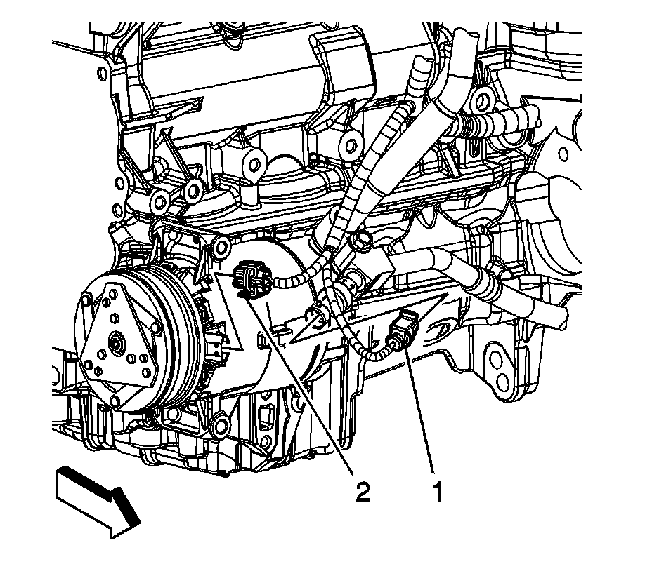
55. Disconnect the air conditioning (A/C) pressure switch electrical connector (1).
56. Disconnect the A/C compressor electrical connector (2).
57. Unbolt and reposition the A/C compressor aside. Secure the compressor with tie straps or mechanics wire.
58. Raise and suitably support the vehicle. Refer to Vehicle Lifting.
59. Drain the engine oil.

60. Remove the engine harness ground bolt (7).
61. Remove the engine harness ground (8) from the engine block.
62. Lower the vehicle.
63. Remove the generator nut (2).
64. Remove the engine harness lead terminal (1) from the generator.