Part 3
Engine Replacement Continued 1 - 73
Installation Procedure

1. Using a engine hoist, remove the engine from the engine stand.
2. Install the following components:
* The engine mount bracket
* The engine block heater, if equipped
* The generator
3. If equipped with a manual transaxle, install the clutch pressure plate and disc.
4. Install the engine to the transaxle.
Notice: Refer to Fastener Notice.
5. If equipped with a automatic transaxle, install the transaxle to engine bolts/stud.
Tighten the bolts/stud to 75 N.m (55 lb ft).

6. If equipped with a manual transaxle, install the transaxle to engine bolts/stud.
Tighten the bolts/stud to 75 N.m (55 lb ft).

7. If equipped with a automatic transaxle, install the transaxle brace and bolts.
Tighten the bolts to 50 N.m (37 lb ft).

8. If equipped with a automatic transaxle, install the torque converter bolts.
Tighten the bolts to 62 N.m (46 lb ft).

9. If equipped with a automatic transaxle, install the torque converter housing access plug.

10. Remove the engine lift hoist from the engine lift hooks.
11. Slide the lift table under the vehicle.
12. Slowly lower the vehicle until it aligns with the alignment marks made during the removal.
13. Install the frame bolts.
Tighten the bolts to 100 N.m (74 lb ft) plus and additional 180 degrees using the J 45059.

14. Install the transaxle mount to transaxle bolts.
15. Tighten the transaxle mount to transaxle bolts in the following sequence.
1. Rear
2. Middle
3. Front
Tighten the bolts to 50 N.m (37 lb ft).

16. Install the engine mount bracket bolts.
17. Tighten the engine mount to bracket bolts in the following sequence.
1. Middle
2. Rear
3. Front
Tighten the bolts to 50 N.m (37 lb ft).
18. Raise the vehicle until the lift table can be removed from under the vehicle.
19. Remove the lift table.

20. Unsecure the radiator assembly from the radiator core support.
21. Install the lower radiator support bolts.
Tighten the bolts to 34 N.m (25 lb ft).

22. Unsecure the wheel drive shaft.
23. Install the J 44394 into the right transaxle output shaft seal.
24. Install the right wheel drive shaft into the transaxle until the drive shaft splines are past the seal, remove the J 44394, then fully install the drive shaft.
25. Verify that the wheel driveshaft is properly engaged:
* Grasp the inner tripot housing and pull the inner housing outward. Do NOT pull on the wheel drive shaft.
* The wheel drive shaft will remain firmly in place when properly engaged.
26. Repeat steps 22 through 25 for the left side.

27. Install the left and right lower ball joints to the steering knuckles.
28. Install the ball joint to steering knuckle bolts and nuts.
* Tighten the nut a first pass to 50 N.m (37 lb ft), then loosen the nut 3/4 of a turn.
* Tighten the nut a final pass to 50 N.m (37 lb ft), plus an additional 30 degrees using the J 45059.

29. Install the left and right outer tie rods to the steering knuckles.
30. Install the NEW left and right steering gear outer tie rod to knuckle nuts.
Tighten the nut to 25 N.m (18 lb ft), plus an additional 90 degrees using the J 45059.

31. Install the left and right stabilizer links to the struts.
32. Install the stabilizer link to strut nuts.
Tighten the nut to 65 N.m (48 lb ft).
33. Left the vehicle.

34. If equipped with a automatic transaxle, install the oil cooler lines to the transaxle.
35. Install the oil cooler line nut.
Tighten the nut to 7 N.m (62 lb in).

36. If equipped with a manual transaxle, install the range selector and shift lever cables to the transaxle bracket.
37. Install the range selector and shift lever cables to the transaxle levers.

38. If equipped with a automatic transaxle, install the range selector lever cable to the transaxle bracket.
39. Connect the range selector lever cable to the transaxle lever.

40. Gather all engine harness branches and position the harness over the engine.
41. If equipped with a manual transaxle perform the following steps. Install the engine harness clip (6) to the transaxle.
42. Connect the engine harness electrical connector (7) to the back up lamp switch.
43. Connect the engine harness electrical connector (4) to the HO2S.
44. Install the engine harness electrical connector clip (5) to the transaxle rear mount bracket.
45. Install the engine harness clip (2) to the transaxle.
46. Install the CPA retainer (3).
47. Connect the engine harness electrical connector (1) to the VSS.

48. If equipped with a automatic transaxle perform the following steps. Connect the engine harness electrical connector (3) to the HO2S.
49. Install the CPA retainer (2).
50. Install the engine harness electrical connector clip (4) to the transaxle rear mount bracket.
51. Install the engine harness clip (1) to the transaxle stud.
52. Connect the engine harness electrical connector (6) to the park neutral position switch.
53. Install the CPA retainer (5).

54. If equipped with a manual transaxle perform the following steps. Connect the engine harness electrical connector (3) to the HO2S.
55. Install the CPA retainer (2).
56. Connect the ECT sensor electrical connector (1).

57. If equipped with a automatic transaxle perform the following steps. Connect the engine harness electrical connector (3) to the HO2S.
58. Install the CPA retainer (2).
59. Connect the ECT sensor electrical connector (1).

60. If equipped with a automatic transaxle, connect the engine harness to the transaxle.

61. If equipped with a automatic transaxle, install the engine harness clip (3) to the speed sensor.
62. Connect the VSS electrical connector (4).
63. Install the engine harness clip (1) to the stud.
64. Install the engine harness clip nut (2) to the engine stud.
Tighten the nut to 10 N.m (89 lb in).

65. Install the engine harness lead terminal (1) to the generator.
66. Install the generator nut (2).
Tighten the nut to 20 N.m (27 lb ft).
67. Raise the vehicle.
68. Position the engine harness ground (8) to the engine block.
69. Install the engine harness ground bolt (7).
Tighten the bolt to 25 N.m (18 lb ft).
70. Unsecure the A/C compressor and position to the engine block. Install the A/C compressor bolts.
Tighten the bolts to 22 N.m (16 lb ft).
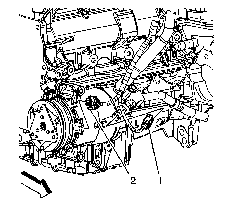
71. Connect the A/C compressor electrical connector (2).
72. Connect the A/C pressure switch electrical connector (1).
73. Raise and support the vehicle.