Air Delivery Description and Operation
Air Delivery Description and Operation
The air delivery controls are divided into 4 areas:
* HVAC Control Components
* Air Speed
* Air Distribution
* Recirculation Operation
HVAC Control Components
HVAC Control Assembly
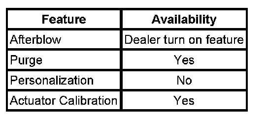
The HVAC control assembly is a non-class 2 device that interfaces between the operator and the HVAC system to maintain air temperature and distribution settings. The battery positive and ignition 3 voltage circuits provide power to the control module. The HVAC control assembly during defrost mode will change the a/c compressor LED status from on to off. The control head displays recirc, outside air, a/c and rear defrost feedback status through LED indicators. The HVAC control head will display NO COMMUNICATION when checking DTCs or doing a vehicle diagnostic system check refer to Diagnostic Trouble Code (DTC) List - Vehicle and Diagnostic System Check - Vehicle. The control module supports the following features:
Mode Actuator
The air temperature actuators are a 5-wire bi-directional electric motor that incorporates a feedback potentiometer. Ignition 3 voltage, low reference, control, 5-volt reference and position signal circuits enable the actuator to operate. The control circuit uses either a 0, 2.5, or 5-volt signal to command the actuator movement. When the actuator is at rest, the control circuit value is 2.5 volts. A 0 or 5-volt control signal commands the actuator movement in opposite directions. When the actuator shaft rotates, the potentiometer's adjustable contact changes the door position signal between 0-5 volts.
The HVAC control module uses a range of 0-255 counts to index the actuator position. The door position signal voltage is converted to a 0-255 count range. When the module sets a commanded, or targeted, value, the control signal is changed to either 0 or 5 volts depending upon the direction that the actuator needs to rotate to reach the commanded value. As the actuator shaft rotates, the changing position signal is sent to the module. Once the position signal and the commanded value are the same, the module changes the control signal to 2.5 volts.
Recirculation Actuator
The recirculation actuator is a 2-wire bi-directional electric motor. Two control circuits enable the actuator to operate. The control circuits use either a 0 or 12-volt value to co-ordinate the actuator movement. When the actuator is at rest, both control circuits have a value of 0 volts. In order to move the actuator, the HVAC control module grounds the appropriate control circuit for the commanded direction. The HVAC control module reverses the polarity of the control circuits to move the actuator in the opposite direction.
The HVAC control module determines the door position by counting motor pulses on one of the control circuits. These pulses are small voltage fluctuations that occur when the brush is shorted across 2 commutator contacts as the motor rotates. As the actuator shaft rotates, the HVAC control module monitors the voltage drop across an internal resistance to detect the pulses. The HVAC control module converts the pulses to counts with a range of 0 to 255 counts. The HVAC control module uses a range of 0-255 counts to index the actuator position.
Air Speed
The HVAC control module applies voltage to the blower motor control circuit that corresponds to the selected blower speed. The resistors and the blower motor are in a series circuit. The following list represents the number of resistors in series with the blower motor per particular speed request:
* Low speed - 4 resistors
* Medium 1 speed - 3 resistors
* Medium 2 speed - 2 resistors
When the operator requests High speed, the HVAC control module applies voltage to the blower motor relay through the high blower motor control circuit. The voltage energizes the blower motor relay, connecting the blower motor to battery positive voltage.
Afterblow
The afterblow is a dealer turn on option. It is inactive in a new vehicle. The afterblow relay resides in the IBCM. The IBCM will directly turn on the hi blower fan relay to start the afterblow process.
Air Distribution
The HVAC control module controls the mode actuator in order to distribute airflow to a desired outlet. When the mode switch is moved to the bi-level through defrost positions, the A/C compressor clutch engages and the recirculation actuator will be moved to the outside air position.
Recirculation Operation
The HVAC control module controls the air intake through the recirculation actuator. Recirculation is not available when the mode is in bi-level through defrost. The operator must activate the blower for Recirculation operation. When recirculation is selected the A/C compressor will be engaged automatically.