Restraints and Safety Systems: Description and Operation
Fig.1 Front Airbag System Component Location:
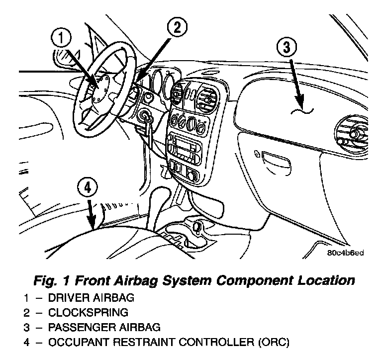
FRONT AIRBAG SYSTEM
A dual front airbag system is standard factory-installed safety equipment on this model. Both the driver and passenger airbag modules are certified to new federal regulations, which allows them to deploy with less force than prior airbags. The primary passenger restraints in this vehicle are the seat belts, which require active use by the vehicle occupants. The front airbag system is a supplemental passive restraint that was designed and is intended to enhance the protection for the front seat occupants of the vehicle when used in conjunction with the seat belts.
The driver airbag module includes an inflatable airbag and an inflator unit behind a trim cover in the hub area of the steering wheel. The passenger airbag module includes a second inflatable airbag and an inflator unit behind an airbag door in the instrument panel above the glove box.
The dual front airbag system consists of the following components:
- Occupant Restraint Controller (ORC)
- Airbag indicator lamp Clockspring
- Driver and passenger airbag modules (including the airbag inflators)
- Wire harness and connections.
See the proper Body Diagnostic Procedures to test or diagnose a problem with any component of the front airbag system.
The front airbag system electrical circuits are continuously monitored and controlled by a microprocessor and software contained within the Occupant Restraint Controller (ORC). The ORC also contains an impact sensor and a safing sensor, which are monitored by the ORC to determine when an impact occurs that is severe enough to require front airbag system protection. When a frontal impact is severe enough, the ORC initiates the inflator units of both front airbag modules to deploy the airbags.
An airbag indicator lamp in the instrument cluster lights for about six to eight seconds as a bulb test each time the ignition switch is turned to the ON position. Following the bulb test, the airbag indicator lamp is turned ON or OFF by the ORC to indicate the status of the airbag system. If the airbag indicator lamp comes ON at any time other than during the bulb test, it indicates that there is a problem in the airbag system circuits. Such a problem may cause the airbags not to deploy when required, or to deploy when not required.
During a frontal vehicle impact, the knee blockers work in concert with properly adjusted seat belts to restrain the driver and front seat passenger in the proper position for an airbag deployment. The knee blockers also work to absorb and distribute the crash energy from the driver and front seat passenger to the structure of the instrument panel. The driver side knee blocker is integral to the left lower instrument panel bezel. The passenger side knee blocker is integral to the glove box door.
Following are general descriptions of the major components in the airbag system.
WARNING:
- THE FRONT AIRBAG SYSTEM IS A SENSITIVE, COMPLEX ELECTROMECHANICAL UNIT. BEFORE ATTEMPTING TO DIAGNOSE OR SERVICE ANY FRONT AIRBAG SYSTEM OR RELATED STEERING WHEEL, STEERING COLUMN, OR INSTRUMENT PANEL COMPONENTS YOU MUST FIRST DISCONNECT AND ISOLATE THE BATTERY NEGATIVE (GROUND) CABLE. THEN WAIT TWO MINUTES FOR THE SYSTEM CAPACITOR TO DISCHARGE BEFORE FURTHER SYSTEM SERVICE. THIS IS THE ONLY SURE WAY TO DISABLE THE AIRBAG SYSTEM.FAILURE TO DO THIS COULD RESULT IN ACCIDENTAL FRONT AIRBAG DEPLOYMENT AND POSSIBLE PERSONAL INJURY.
- THE DRIVER AIRBAG MODULE INFLATOR ASSEMBLY CONTAINS PYROTECHNIC MATERIALS THAT ARE POISONOUS AND EXTREMELY FLAMMABLE. CONTACT WITH ACID, WATER, OR HEAVY METALS MAY PRODUCE HARMFUL AND IRRITATING GASES OR COMBUSTIBLE COMPOUNDS. THE PASSENGER AIRBAG MODULE CONTAINS PRESSURIZED ARGON GAS. DO NOT ATTEMPT TO DISMANTLE AN AIRBAG MODULE OR TAMPER WITH ITS INFLATOR. DO NOT PUNCTURE, INCINERATE, OR BRING INTO CONTACT WITH ELECTRICITY. DO A NOT STORE AT TEMPERATURES EXCEEDING 93 °C(20 °F).
- REPLACE FRONT AIRBAG SYSTEM COMPONENTS ONLY WITH PARTS SPECIFIED IN THE CHRYSLER MOPAR PARTS CATALOG. SUBSTITUTE PARTS MAY APPEAR INTERCHANGEABLE, BUT INTERNAL DIFFERENCES MAY RESULT IN INFERIOR OCCUPANT PROTECTION.
- THE FASTENERS, SCREWS, AND BOLTS ORIGINALLY USED FOR THE FRONT AIRBAG SYSTEM COMPONENTS HAVE SPECIAL COATINGS AND ARE SPECIFICALLY DESIGNED FOR THE FRONT AIRBAG SYSTEM. THEY MUST NEVER BE REPLACED WITH ANY SUBSTITUTES. ANY TIME A NEW FASTENER IS NEEDED, REPLACE IT WITH THE CORRECT FASTENERS PROVIDED IN THE SERVICE PACKAGE OR SPECIFIED IN THE CHRYSLER MOPAR PARTS CATALOG.
- WHEN A STEERING COLUMN HAS AN AIRBAG MODULE ATTACHED, NEVER PLACE THE COLUMN. ON THE FLOOR OR ANY OTHER SURFACE WITH THE STEERING WHEEL OR AIRBAG MODULE FACE DOWN.
- DO NOT PLACE A NON-DEPLOYED AIRBAG FACE DOWN ON A HARD SURFACE, THE AIRBAG WILL PROPEL INTO THE AIR IF ACCIDENTALLY A DEPLOYED, AND COULD RESULT IN SERIOUS OR FATAL INJURY.
Fig.2 Occupant Restraint Controller (ORC) Location:

OCCUPANT RESTRAINT CONTROLLER (ORC)
The Occupant Restraint Controller (ORC) is mounted on the tunnel floor pan, between the transmission shifter and parking brake.
The ORC contains a microprocessor, the impact sensor, and energy storage capacitors. The microprocessor contains the airbag system logic. The airbag system logic includes On-Board Diagnostics (OBD) capability, and communicates with the instrument cluster circuitry on the Programmable Communication Interface (PCI) data bus to control the airbag indicator lamp.
The accelerometer is located inside the ORC. The accelerometer provides confirmation of a crash, discriminating severity. The ORC monitors the system to determine the system readiness. The ORC contains on-board diagnostics, and will illuminate the AIRBAG warning lamp on the cluster when a fault occurs. The warning equipment is tested for a few seconds every time the vehicle is started.
The microprocessor on the ORC monitors the impact sensor signal and the airbag system electrical circuits to determine the system readiness If the ORC detects a monitored system fault, it sends messages to the instrument cluster over the PCI bus to turn ON the airbag warning lamp. A pre-programmed decision algorithm in the ORC microprocessor determines when the deceleration rate is severe enough to require airbag system protection. When the programmed conditions are met, the ORC sends an electrical signal to deploy the airbag system airbag modules. The impact sensor is an accelerometer that senses the rate of vehicle deceleration, which provides verification of the direction and severity of an impact. The ORC is calibrated for the specific vehicle, and is only serviced as a unit. The ORC also contains an energy-storage capacitor. The purpose of the capacitor is to provide airbag system protection if the impact has damaged or disconnected the battery. The ORC cannot be repaired or adjusted, and if damaged or faulty, must be replaced.
WARNING:
- THE FRONT AIRBAG SYSTEM IS A SENSITIVE,COMPLEX ELECTROMECHANICAL UNIT. BEFORE ATTEMPTING TO DIAGNOSE OR SERVICE ANY FRONT AIRBAG SYSTEM OR RELATED STEERING WHEEL, STEERING COLUMN, OR INSTRUMENT PANEL COMPONENTS YOU MUST FIRST DISCONNECT AND ISOLATE THE BATTERY NEGATIVE (GROUND) CABLE. THEN WAIT TWO MINUTES FOR THE SYSTEM CAPACITOR TO DISCHARGE BEFORE FURTHER SYSTEM SERVICE. THIS IS THE ONLY SURE WAY TO DISABLE THE FRONT AIRBAG SYSTEM. FAILURE TO DO THIS COULD RESULT IN ACCIDENTAL FRONT AIRBAG DEPLOYMENT AND POSSIBLE PERSONAL INJURY.
- REPLACE FRONT AIRBAG SYSTEM COMPONENTS ONLY WITH PARTS SPECIFIED IN THE CHRYSLER MOPAR PARTS CATALOG. SUBSTITUTE PARTS MAY APPEAR INTERCHANGEABLE, BUT INTERNAL DIFFERENCES MAY RESULT IN INFERIOR OCCUPANT PROTECTION.
- THE FASTENERS, SCREWS, AND BOLTS ORIGINALLY USED FOR THE FRONT AIRBAG SYSTEM COMPONENTS HAVE SPECIAL COATINGS AND ARE SPECIFICALLY DESIGNED FOR THE FRONT AIRBAG SYSTEM. THEY MUST NEVER BE REPLACED WITH ANY SUBSTITUTES. ANY TIME A NEW FASTENER IS NEEDED, REPLACE IT WITH THE CORRECT FASTENERS PROVIDED IN THE SERVICE PACKAGE OR SPECIFIED IN THE CHRYSLER MOPAR PARTS CATALOG.
Fig.3 Clockspring Location:
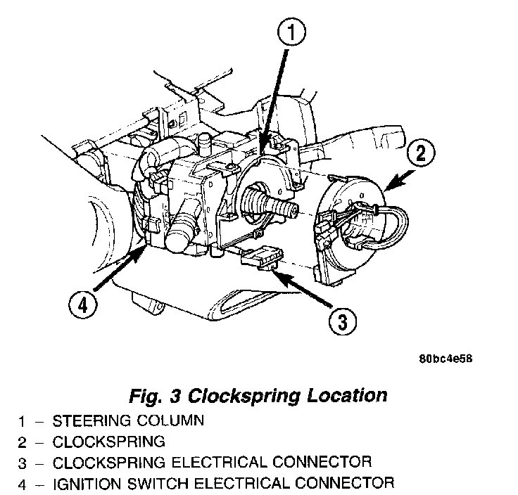
CLOCKSPRING
The clockspring is mounted on the steering column behind the steering wheel. This assembly consists of a flat, ribbon like, electrically conductive tape that winds and unwinds with the steering wheel rotation.
It is used to maintain a continuous electrical circuit between the wiring harness and the Driver Airbag Module.
The clockspring must be properly centered when it is installed on the steering column following any service removal, or it will be damaged. See the Clockspring Centering procedure for more information.
The clockspring cannot be repaired. If the clock-spring is faulty, damaged, or if the airbag has been deployed, the clockspring must be replaced.
WARNING:
- THE FRONT AIRBAG SYSTEM IS A SENSITIVE,COMPLEX ELECTROMECHANICAL UNIT. BEFORE ATTEMPTING TO DIAGNOSE OR SERVICE ANY FRONT AIRBAG SYSTEM OR RELATED STEERING WHEEL, STEERING COLUMN, OR INSTRUMENT PANEL COMPONENTS YOU MUST FIRST DISCONNECT AND ISOLATE THE BATTERY NEGATIVE (GROUND) CABLE. THEN WAIT TWO MINUTES FOR THE SYSTEM CAPACITOR TO DISCHARGE BEFORE FURTHER SYSTEM SERVICE. THIS IS THE ONLY SURE WAY TO DISABLE THE FRONT AIRBAG SYSTEM. FAILURE TO DO THIS COULD RESULT IN ACCIDENTAL FRONT AIRBAG DEPLOYMENT AND POSSIBLE PERSONAL INJURY.REPLACE FRONT AIRBAG SYSTEM COMPONENTS ONLY WITH PARTS SPECIFIED IN THE CHRYSLER MOPAR PARTS CATALOG. SUBSTITUTE PARTS MAY APPEAR INTERCHANGEABLE, BUT INTERNAL DIFFERENCES MAY RESULT IN INFERIOR OCCUPANT PROTECTION.
- THE FASTENERS, SCREWS, AND BOLTS ORIGINALLY USED FOR THE FRONT AIRBAG SYSTEM COMPONENTS HAVE SPECIAL COATINGS AND ARE SPECIFICALLY DESIGNED FOR THE FRONT AIRBAG SYSTEM. THEY MUST NEVER BE REPLACED WITH ANY SUBSTITUTES. ANY TIME A NEW FASTENER IS NEEDED, REPLACE IT WITH THE CORRECT FASTENERS PROVIDED IN THE SERVICE PACKAGE OR SPECIFIED IN THE CHRYSLER MOPAR PARTS CATALOG.
Fig.4 Driver Airbag Module Location:
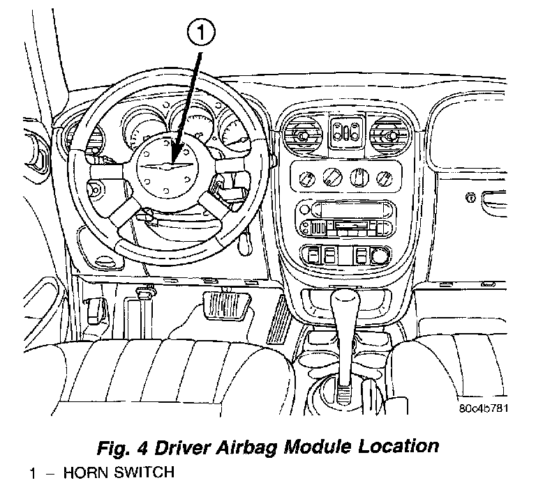
Fig.5 Driver Airbag Module/Cover/Horn Switch:
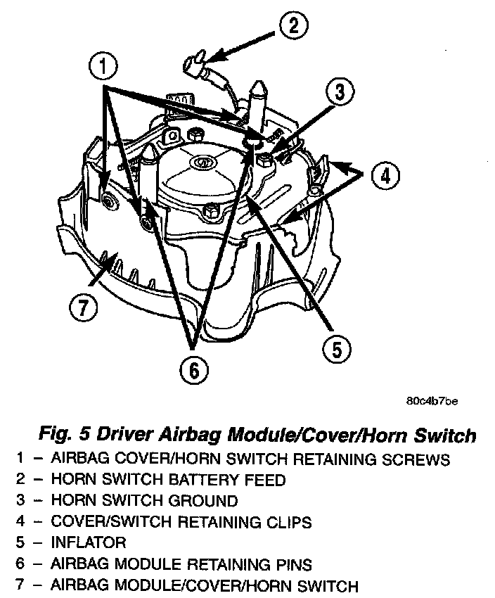
DRIVER AIRBAG MODULE
WARNING: DO NOT PLACE A NON-DEPLOYED AIR-BAG FACE DOWN ON A HARD SURFACE, THE AIR-BAG WILL PROPEL INTO THE AIR IF ACCIDENTALLY DEPLOYED, AND COULD RESULT IN SERIOUS OR FATAL INJURY.
The driver airbag module protective trim cover is the most visible part of the driver airbag system. The driver airbag module is mounted directly to the steering wheel. Located under the airbag module trim cover are the horn switch, the folded airbag cushion, and the airbag cushion supporting components. The resistive membrane-type horn switch is secured within a plastic tray between the driver airbag module cover and the backer plate which is heat staked on to the driver airbag module cover.
The driver airbag module cannot be repaired, and must be replaced if deployed or in any way damaged.
The driver airbag module trim cover and the horn switch are available for service replacement.
The driver airbag module includes a stamped metal housing to which the cushion and an inflator unit are attached and sealed. The conventional pyrotechnic-type inflator assembly is mounted to studs on the back of the airbag module housing. The inflator seals the hole in the airbag cushion so it can discharge the gas it produces directly into the cushion when supplied with the proper electrical signal. Following an airbag deployment, the airbag cushion quickly deflates by venting this gas towards the instrument panel through the porous fabric material used on the steering wheel side of the airbag cushion.
The protective trim cover is fitted to the front of the airbag module and forms a decorative cover in the center of the steering wheel. The inside of the trim cover has locking blocks molded into it that engage a lip on the airbag module metal housing. Two stamped metal retainers then fit over the inflator mounting studs on the back of the airbag module housing and are engaged in slots on the inside of the cover, securely locking the trim cover into place. The trim cover will split at predetermined breakout lines, then fold back out of the way along with the horn switch and tray unit upon airbag deployment.
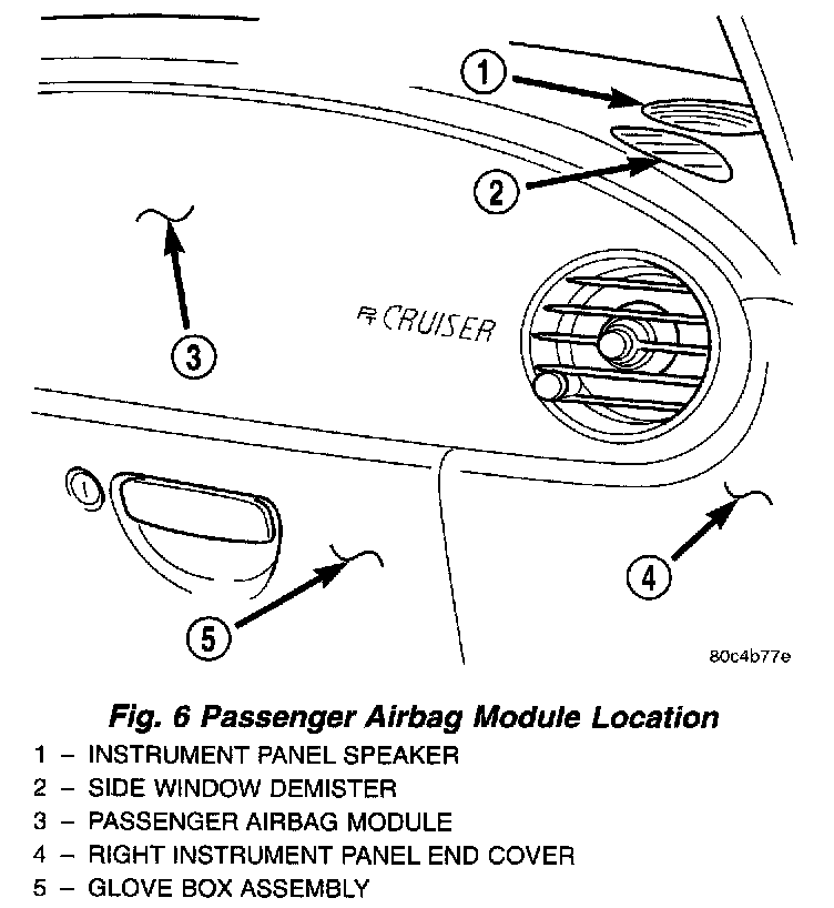
Fig.6 Passenger Airbag Module Location:
PASSENGER AIRBAG MODULE
WARNING: DO NOT PLACE A NON-DEPLOYED AIR-BAG FACE DOWN ON A HARD SURFACE5 THE AIR-BAG WILL PROPEL INTO THE AIR IF ACCIDENTALLY DEPLOYED, AND COULD RESULT IN SERIOUS OR FATAL INJURY.
The passenger airbag module is located behind the passenger airbag module cover, between the glove box and instrument panel top cover.
The passenger airbag module includes a stamped steel housing within which the cushion and inflator are mounted and sealed. Two stamped metal brackets, one on each end of the housing, enclose the cushion and inflator. The mounting scheme consists of two weld studs and a bracket with two tabs off the bottom of the housing.
Following a passenger airbag deployment, the passenger airbag module and the passenger airbag module cover must be replaced. If inspection reveals that the passenger airbag module mounting points on the instrument panel structural duct have been cracked or damaged, the instrument panel assembly must also be replaced. The passenger airbag module cannot be repaired, and must be replaced if deployed or in any way damaged.
The hybrid-type inflator assembly includes a small canister of highly compressed argon gas. The inflator seals the hole in the airbag cushion so it can discharge the gas it produces directly into the cushion when supplied with the proper electrical signal. Following an airbag deployment, the airbag cushion quickly deflates by venting this gas through the porous fabric material used on each end panel of the airbag cushion.
The passenger airbag module is secured with screws to the instrument panel structural duct beneath the instrument panel top pad and above the glove box opening.
SIDE IMPACT AIRBAG SYSTEM
Vehicles equipped with the Side Impact Airbag System utilize two airbags mounted to each front seat back frame. This system designed to protect occupants in the event of a side impact collision.
The side impact airbag control module (SIACM) controls the seat back mounted airbags. If the SIACM determines the impact is severe enough, the appropriate airbag's will inflate, tearing open the front seat back trim cover/s protecting the passenger/s. Once a seat back mounted airbag has been deployed, all damaged parts must be replaced.
WARNING:
- THE SIDE IMPACT AIRBAG SYSTEM CONTAINS SENSITIVE, COMPLEX ELECTRO-MECHANICAL UNITS. BEFORE ATTEMPTING TO DIAGNOSE OR SERVICE ANY SIDE IMPACT AIRBAG SYSTEM COMPONENTS, YOU MUST FIRST DISCONNECT AND ISOLATE THE BATTERY NEGATIVE (GROUND) CABLE. THIS IS THE ONLY SURE WAY TO DISABLE THE SIDE IMPACT AIRBAG SYSTEM. FAILURE TO DO THIS COULD RESULT IN ACCIDENTAL SIDE IMPACT AIRBAG MODULE DEPLOYMENT AND P05SIBLE PERSONAL INJURY. DO NOT PLACE A NON-DEPLOYED SIDE AIRBAG FACE DOWN ON A HARD SURFACE, THE AIR-BAG WILL PROPEL INTO THE AIR IF ACCIDENTALLY DEPLOYED, AND COULD RESULT IN SERIOUS OR FATAL INJURY. BEFORE SERVICING A SIDE IMPACT AIRBAG CONTROL MODULE (SIACM), ALWAYS DISCONNECT THE APPROPRIATE (LEFT OR RIGHT) SIDE IMPACT AIRBAG CONNECTOR UNDER THE SEAT TO ENGAGE THE SIDE IMPACT AIRBAG SYSTEM SHORTING BAR TO PREVENT ACCIDENTAL DEPLOYMENT.
- DO NOT ATTEMPT TO DISMANTLE A SIDE IMPACT AIRBAG MODULE OR TAMPER WITH ITS INFLATOR. DO NOT PUNCTURE, INCINERATE, OR BRING INTO CONTACT WITH ELECTRICITY. DO NOT STORE AT TEMPERATURES EXCEEDING 93 °C(200 °F).
- REPLACE SIDE IMPACT AIRBAG SYSTEM COMPONENTS ONLY WITH PARTS SPECIFIED IN THE CHRYSLER MOPAR PARTS CATALOG. SUBSTITUTE PARTS MAY APPEAR INTERCHANGEABLE, BUT INTERNAL DIFFERENCES MAY RESULT IN INFERIOR OCCUPANT PROTECTION.
- THE FASTENERS, SCREWS, AND BOLTS ORIGINALLY USED FOR THE SIDE IMPACT AIRBAG SYSTEM COMPONENTS HAVE SPECIAL COATINGS AND ARE SPECIFICALLY DESIGNED FOR THE SIDE IMPACT AIRBAG SYSTEM. THEY MUST NEVER BE REPLACED WITH ANY SUBSTITUTES. ANY TIME A NEW FASTENER IS NEEDED, REPLACE IT WITH THE CORRECT FASTENERS PROVIDED IN THE SERVICE PACKAGE OR SPECIFIED IN THE CHRYSLER MOPAR PARTS CATALOG.
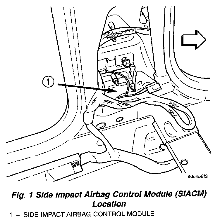
SIDE IMPACT AIRBAG CONTROL MODULE (SIACM)
Vehicles equipped with side impact airbags use two side impact airbag control modules. One is located on each side of the vehicle within the body B-pillar.
Each side impact airbag control module (SIACM) serves as the impact sensor for its seat mounted airbag. The right side SIACM controls the right seat airbag. The left side SIACM controls the left seat airbag. Each SIACM contains two accelerometers, both accelerometers must agree in order to deploy the side airbag. In the event of a side impact, the appropriate SIACM will send a electronic signal to its airbag, deploying the airbag. The SIACM communicates with the Occupant Restraint Controller (ORC) via the PCI bus circuit.
The SIACM perform self-diagnostics and circuit tests to determine if the system is functioning properly. If the test finds a problem, the SIACM will set both active and stored Diagnostic Trouble Codes (DTC's). If a DTC is active, the SIACM will request that the airbag warning lamp be turned on. The results of the system test are transmitted on the PCI bus circuit to the ORC once each second, or on a change in lamp state (ON/OFF). If the warning lamp status message from either SIACM contains a lamp ON request, the ORC will set an active DTC. At the same time as the DTC is set, the ORC sends a PCI bus message to the cluster requesting the airbag warning lamp to be turned ON. Observe all ORC WARNING and CAUTION statements when servicing or handling the SIACM. The SIACM's are not serviceable and must be replaced even if they are dropped.
Fig.1 Side Impact Airbag Control Module (SIACM) Location:
SIDE IMPACT AIRBAG MODULES
WARNING: DO NOT PLACE A NON-DEPLOYED SIDE AIRBAG FACE DOWN ON A HARD SURFACE, THE AIRBAG WILL PROPEL INTO THE AIR IF ACCIDENTALLY DEPLOYED, AND COULD RESULT IN SERIOUS OR FATAL INJURY.
The left and right seat airbag modules are located in the outboard end of the front seat backs. The air-bag contains a bag, an inflator (small canister of highly compressed gas), and a mounting bracket. the seat airbag module cannot be repaired and must be replaced if deployed or in any way damaged.
When supplied with the proper electrical signal, the inflator seals the hole in the airbag cushion so it can discharge the compressed gas it contains directly into the cushion. Upon deployment, the seat back trim cover will tear open and allow the seat airbag to fully deploy between the seat and the door.
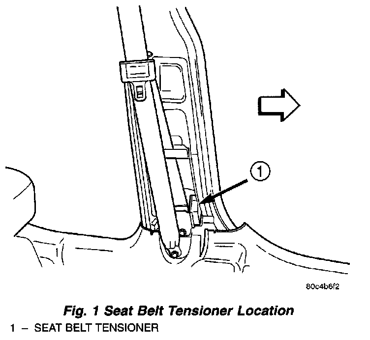
Fig.1 Seat Belt Tensioner Location:
SEAT BELT TENSIONER SYSTEM
The seat belt system incorporates Tensioner Modules. They are integral to the seat belt retractors and cannot be serviced. If found defective they must be replaced.
At the onset of an impact event, each tensioner uses a pyrotechnic device which is triggered simultaneously with the airbags to rapidly retract the seat belts. With the slack removed, the occupant's forward motion in an impact will be reduced as will the likelihood of contacting interior components. After an impact that deploys the airbags, the seat belt tensioner assembly must be replaced.
The Occupant Restraint Controller (ORC) monitors the seat belt tensioner circuit resistance and reports active and stored Diagnostic Trouble Codes (DTC's) if any problem is found.
Once a vehicle has been in an accident, the tensioner will have a "Grave1/Grinding" sound to it after the tensioner has been put into use. This must be replaced along with any deployed airbags and broken or damaged parts.
WARNING: WHEN THE FRONT AIRBAG IS DEPLOYED, THE TENSIONER WILL HAVE DEPLOYED ALSO AND SHOULD BE REPLACED.DIAGNOSIS AND TESTING SEAT BELT TENSIONER
Use a DRBIII(R) scan tool and the proper Body Diagnostic Procedure for Diagnosis and Testing.