With Automatic Transaxle
PEDAL WITH AUTOMATIC TRANSAXLEREMOVAL
NOTE: Before proceeding, Refer to Service Precautions.
1. Unclip the air cleaner cover (two clips) and move the cover aside.
2. Disconnect and isolate the battery negative cable from its post on the battery.
3. Remove the silencer pad below the knee blocker.
4. Fold down and remove the knee blocker.
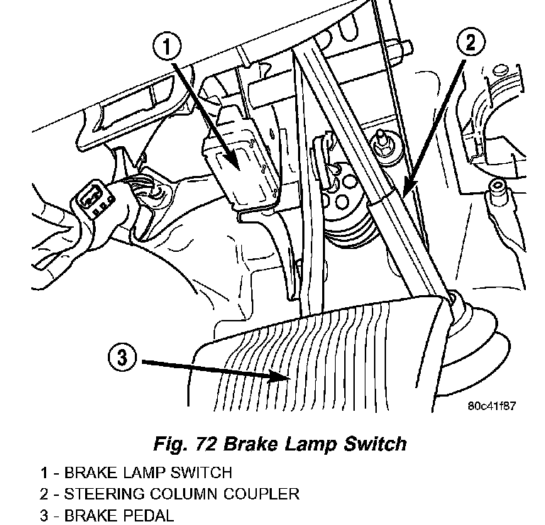
5. Remove the brake lamp switch by rotating the switch in a counterclockwise direction approximately 30 degrees.
6. Pull the switch rearward and remove it from its mounting bracket. Discard the brake lamp switch.
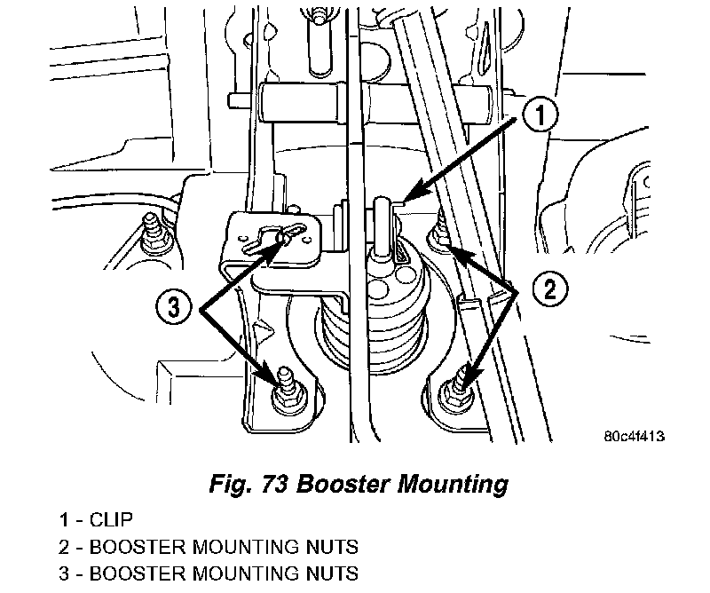
7. Remove the clip securing the power brake booster input rod to the brake pedal. Remove the input rod from the brake pedal.
8. Remove the four nuts securing the power brake booster to the brake pedal bracket.
9. Remove the two remaining upper nuts securing the brake pedal bracket to the instrument panel support.
10. Carefully remove the brake pedal and bracket assembly from the vehicle.
11. Remove the pivot shaft nut.
12. Remove the pivot shaft out the right side of the bracket.
13. Slide the pedal out of its bracket.
14. The bushings can be removed from the pedal by sliding them out each side of the pivot.
INSTALLATION
1. Lubricate the brake pedal bushings with Mopar Lubriplate or an equivalent.
2. If removed, slide a bushing in each side of the pedal until the bushing shoulder contacts the pedal pivot.
3. Install the brake pedal and bushings into the pedal mounting bracket by sliding the pedal between the sides of the bracket behind the brake lamp switch mounting flange.
4. Once the pedal bushings line up with the mounting holes in the bracket, install the pivot shaft through the pedal from the right side.
5. Install the pivot shaft nut. Tighten the nut to a torque of 34 Nm (25 ft. lbs.).
6. Carefully install the brake pedal and bracket assembly in the vehicle lining up the bracket with the power brake booster mounting studs and the studs on the instrument panel support.
7. Install the two upper nuts securing the brake pedal bracket to the instrument panel support. Install the two nuts all the way, but do not tighten them at this time.
8. Install the four nuts securing the power brake booster to the brake pedal bracket. Tighten the four nuts to a torque of 34 Nm (300 in. lbs.).
9. Tighten the two upper nuts securing the brake pedal bracket to the instrument panel support to a torque of 34 Nm (300 in. lbs.).
10. Install the power brake booster input rod on the pin mounted on the side of the brake pedal. Install a new retaining clip on the end of the pin. Do not reuse the old clip.
CAUTION: Do not reuse the original brake lamp switch. The switch can only be adjusted once. That is during initial installation of the switch. If the switch is not adjusted properly or has been removed for some service, a new switch must be installed and adjusted.
11. Mount and adjust the NEW brake lamp switch using the following procedure:
- Install the switch in its bracket by aligning the index tab on the switch with the slot in the mounting bracket.
- When the switch is fully seated in its bracket, rotate the switch clockwise approximately 30° to lock the switch into place.
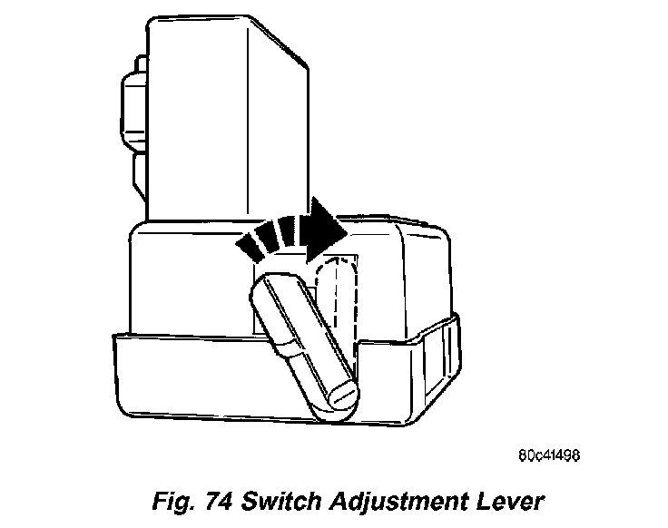
- With the brake pedal in the fully released position, move the lever on the back of the brake lamp switch from the non-adjusted angle position to the full vertical position. This will adjust the brake lamp switch to the vehicle.
12. Install the knee blocker.
13. Install the silencer pad below the knee blocker.
14. Reconnect the battery negative terminal.
15. Reinstall the air cleaner cover (two clips).
16. Check the stop lamps to verify they are operating properly and not staying on when the pedal is in the released position.
17. Road test the vehicle to ensure proper operation of the brakes and speed control (if equipped).