Control Arm: Service and Repair
REMOVAL - LOWER CONTROL ARMNOTE: Before proceeding, Refer to Service Precautions.
1. Raise the vehicle.
2. Remove the front tire and wheel assembly.
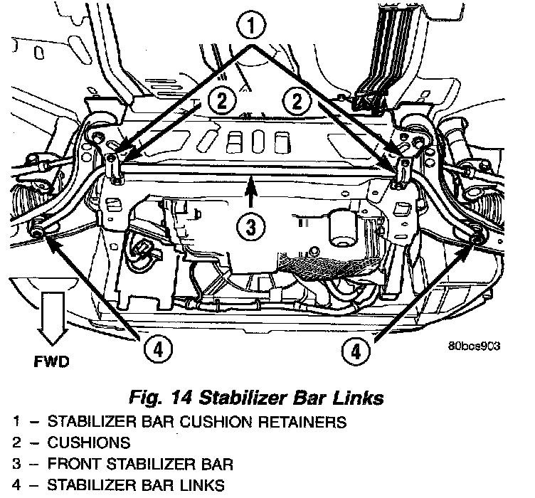
3. Remove both stabilizer bar links from the vehicle. Remove each link by holding the upper retainer/nut with a wrench and turning the link bolt.
4. Rotate the forward ends of the stabilizer bar downward. It may be necessary to loosen the stabilizer bar cushion retainer bolts a little to ease any turning resistance.
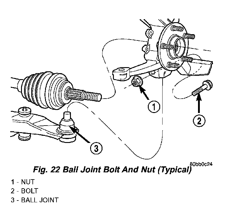
5. Remove the nut and pinch bolt clamping the ball joint stud to the steering knuckle.
CAUTION: After removing the steering knuckle from the ball joint stud, do not pull outward on the knuckle. Pulling the steering knuckle outward at this point can separate the inner ON joint on the driveshaft.
NOTE: Use caution when separating the ball joint stud from the steering knuckle, so the ball joint seal does not get cut.
6. Separate the ball joint stud from the steering knuckle by prying down on lower control arm and up against the ball joint boss on the steering knuckle.
7. If the right lower control arm is being serviced, perform the following:
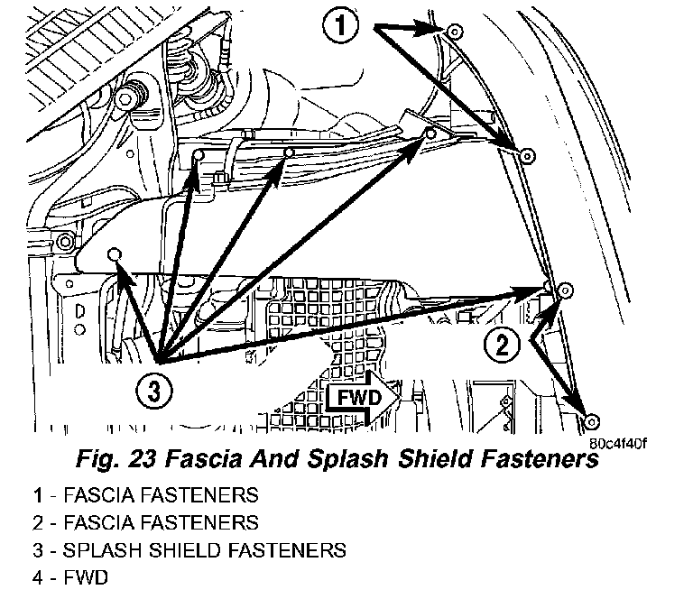
a. Remove the screws fastening the front fascia to the reinforcement as necessary in order to access the drive-belt splash shield forward fastener screw.
b. Remove the drive-belt splash shield fasteners. Remove the shield.
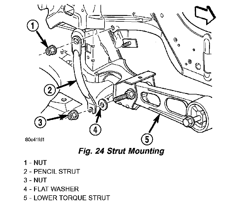
c. Remove the pencil strut from the right front corner of the crossmember and body of the vehicle. Remove the washer behind the strut from the torque strut bolt.
d. Remove the bolts mounting the engine torque strut in place, then remove the engine torque strut from the vehicle.
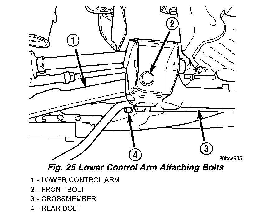
8. Remove the front pivot bolt attaching the lower control arm to the front suspension crossmember. Remove the rear pivot bolt attaching the lower control arm to the front suspension crossmember and frame rail. Remove the lower control arm from the crossmember.
DISASSEMBLY - LOWER CONTROL ARM (BALL JOINT)
NOTE: The removal and installation of the lower ball joint from the lower control arm is to be done with the lower control arm removed from the vehicle.
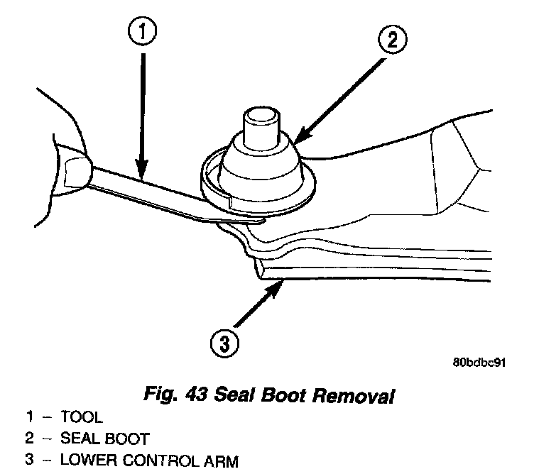
1. Using a screwdriver or other suitable tool, pry the seal boot off of the ball joint.
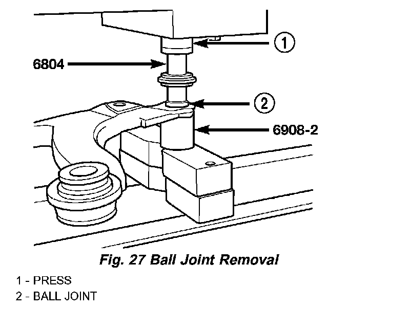
2. Position the Receiver, Special Tool 6908-2, on a hydraulic press to support the lower control arm. Place the control arm on top of Tool 6908-2 so that the bottom of the ball joint sets into the Receiver cup.
3. Place the larger end of the Adapter, Special Tool 6804, on top of the ball joint as shown.
4. Using the hydraulic press, press the ball joint completely out of the lower control arm, into the receiver.
5. Remove the tools, ball joint and arm from the hydraulic press.
DISASSEMBLY - LOWER CONTROL ARM (REAR ISOLATOR BUSHING)
NOTE: The removal and installation of the rear isolator bushing from the lower control arm is only to be done with the lower control arm removed from the vehicle. The front isolator bushing is not serviceable.
1. Install the Remover Receiver, Special Tool 8373-1, into the cup of the Ball Joint Press, Special Tool C-4212F, and tighten the set screw. Install the Remover Driver, Special Tool 8373-2, on the tip of the Ball Joint Press screw-drive.
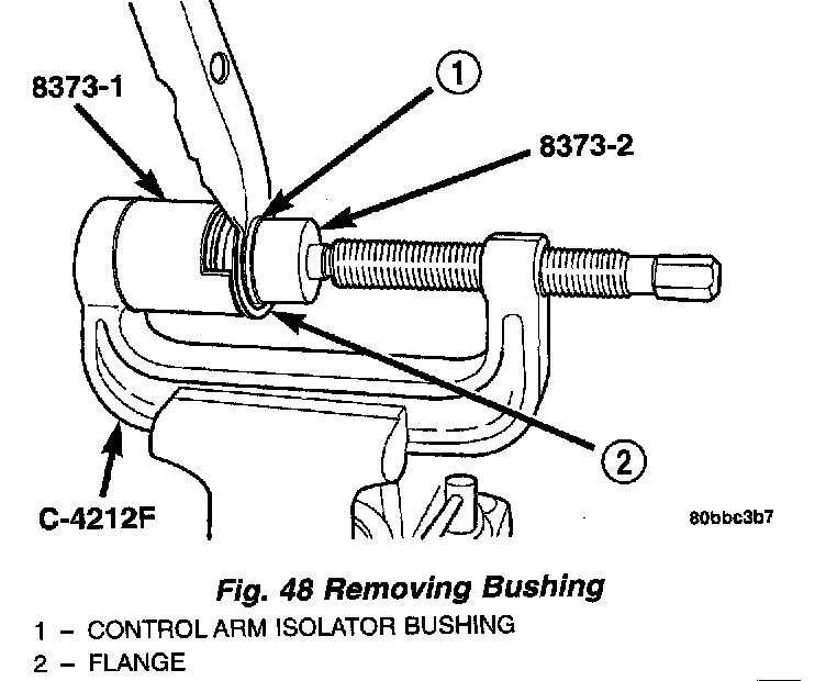
2. Place the lower control arm outer flange against the Receiver as shown. Tighten the screw-drive until the Driver contacts the outer circumference of the bushing evenly. Continue to tighten the screw-drive until the bushing is pressed completely out of the lower control arm.
3. Back off the screw-drive and remove the lower control arm and isolator bushing from the Receiver.
4. Remove the driver 8373-2 and receiver 8373-1 from the ball joint press C-4212F.
ASSEMBLY - LOWER CONTROL ARM (BALL JOINT)
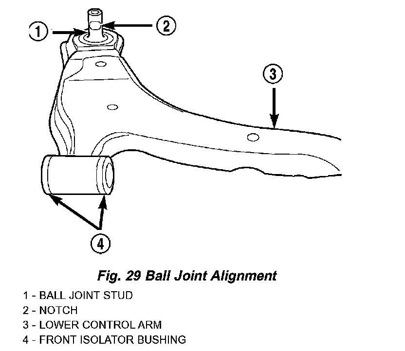
CAUTION: When installing a ball joint in its mounting hole in the lower control arm, position the ball joint so the notch in the ball joint stud is facing the lower control arm front isolator bushing. This will ease assembly of the ball joint to the steering knuckle when the installation of the pinch bolt is attempted.
1. By hand, position ball joint into it's bore on the lower control arm. To avoid binding upon installation, be sure the ball joint is not cocked in the bore.
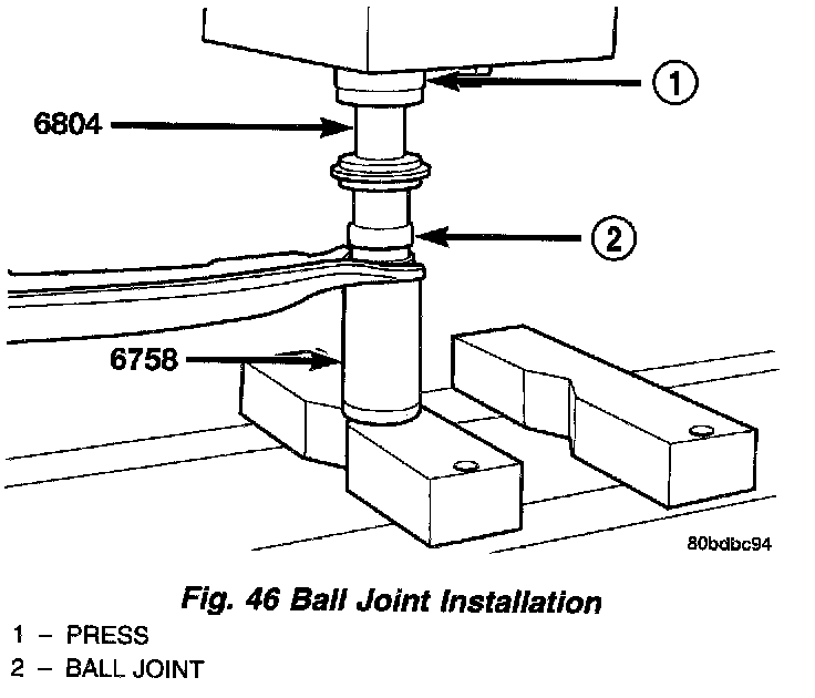
2. Position the Installer, Special Tool 6758, on a hydraulic press to support the lower control arm. Place the control arm on top of Tool 6758 in the upside-down position, aligning the ball joint stud squarely with the Installer's cup.
3. Place the larger end of the Adapter, Special Tool 6804, on top of the ball joint as shown.
4. Using the hydraulic press, press the ball joint into the lower control arm until the shoulder on the ball joint bottoms against the lower control arm ball joint bore. Do not apply excessive pressure against ball joint and lower control arm once the ball joint bottoms.
5. Remove the tools and arm from the hydraulic press.
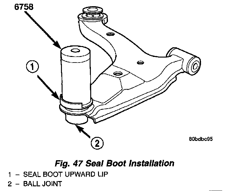
CAUTION: When installing the sealing boot on the ball joint, position the upward lip on the outside perimeter of the seal boot outward, away from the control arm once installed. It is there to help shield heat from the sealing boot.
6. Place a new ball joint seal boot over the ball joint stud. The upward lip located on the outside perimeter of the seal boot must point outward away from the control arm once installed. Start the sealing boot over the sides of the ball joint by hand.
7. Position the Installer, Special Tool 6758, over the sealing boot outer diameter as shown. By hand, apply pressure to the top of the Installer until the seal boot is pressed squarely down against the top surface of lower control arm.
8. Remove the tool.
9. If not already installed, install standard zirc type grease fitting in ball joint.
CAUTION: It is important to lubricate the ball joint before installation of steering knuckle to allow proper venting when the seal is filled. If the ball joint is lubricated after installation to knuckle, damage to the seal can occur.
10. Using a hand operated pump grease gun, fill the ball joint seal boot with Mopar Multi-Mileage Lube or equivalent until grease pushes out past ball joint stem. Wipe off overfill.
11. Install the lower control arm.
ASSEMBLY - LOWER CONTROL ARM (REAR ISOLATOR BUSHING)
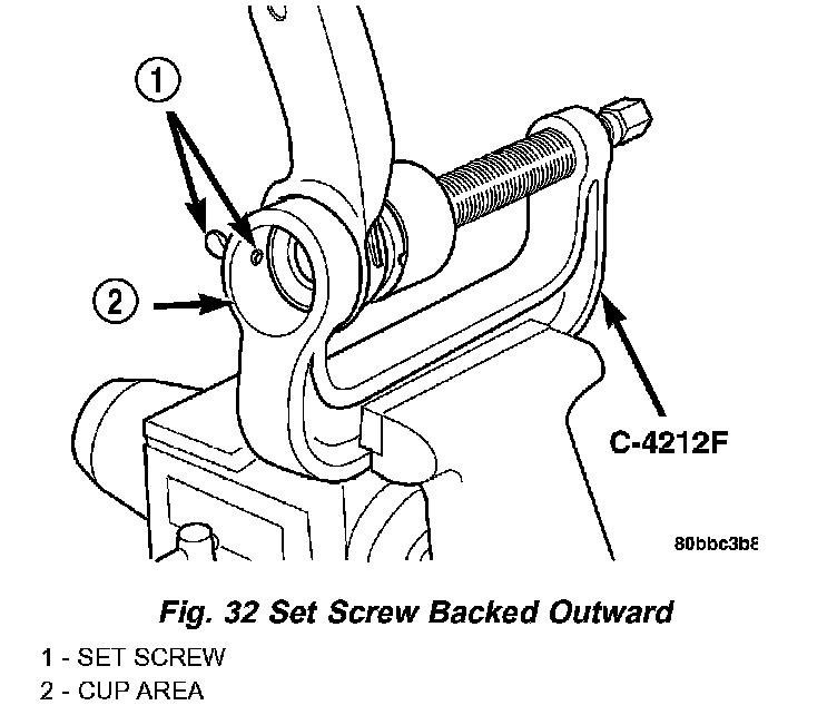
1. Back the ball joint press C-4212F set screw outward so it does not extend out into the cup area.
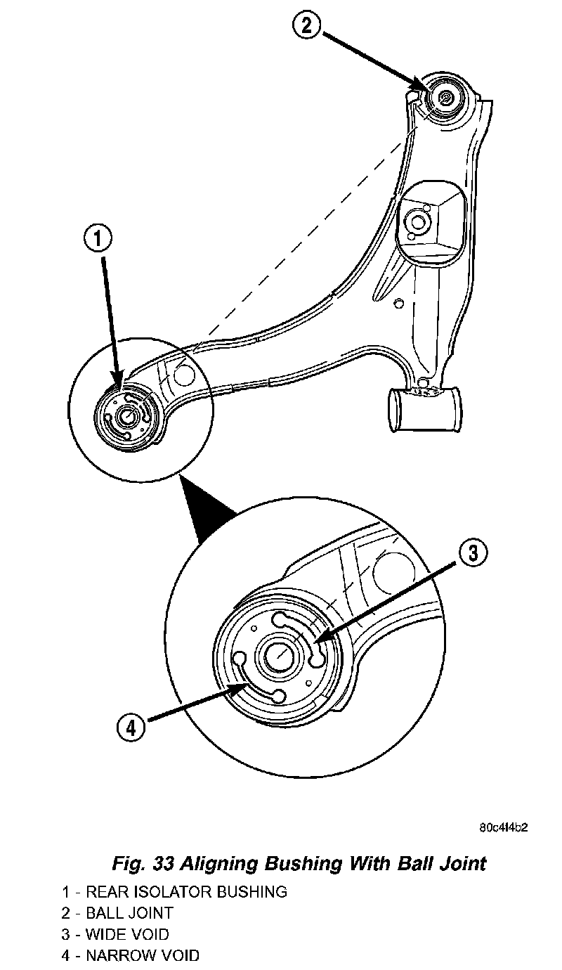
2. Start the bushing in the lower control arm bushing bore by hand. Position the bushing so the voids in the rubber are aligned in relationship to the ball joint as shown. Place the larger void toward the ball joint.
3. Install the Receiver, Special Tool 6760, on the tip of the Ball Joint Press screw drive.
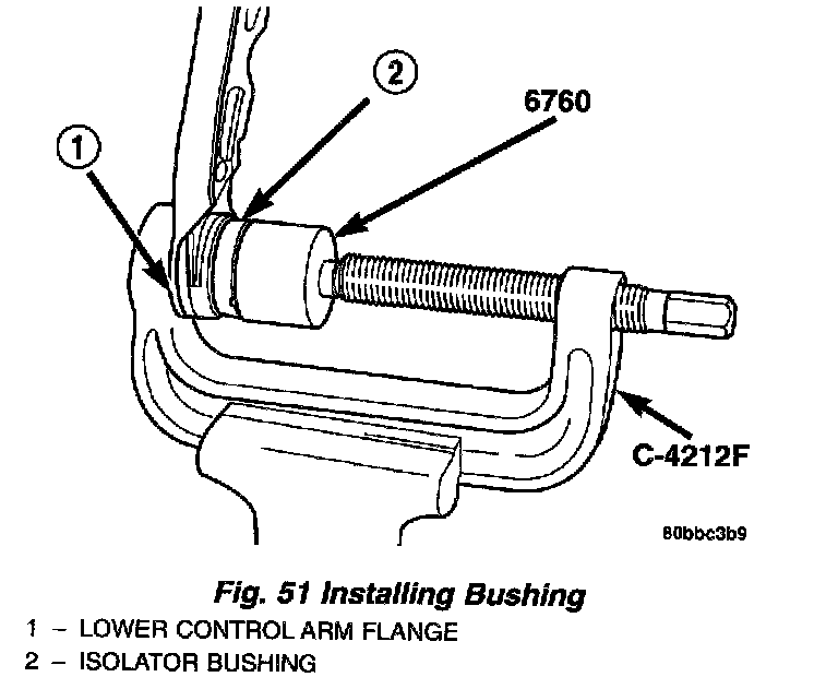
4. Place the lower control arm flange against the cup area of the ball joint press and tighten the screw drive until the Receiver contacts the outer circumference of the bushing. Slowly tighten the screw-drive until the bushing bottoms in the lower control arm bushing bore.
5. Back off the Ball Joint Press screw-drive and remove the power steering gear from the press.
6. Install the lower control arm on the vehicle.
INSTALLATION - LOWER CONTROL ARM
1. Position the lower control arm into the crossmember. Install, but do not fully tighten, the rear pivot bolt attaching the lower control arm to the front suspension crossmember and frame rail. Install, but do not fully tighten, the front pivot bolt attaching the lower control arm to the front suspension crossmember.
2. With no weight on the lower control arm, tighten the lower control arm rear pivot (and suspension crossmember) bolt to a torque of 250 Nm (185 ft. lbs.), then tighten the lower control arm front pivot bolt to a torque of 170 Nm (125 ft. lbs.).
3. Install the ball joint stud into the steering knuckle aligning the bolt hole in the knuckle boss with the notch formed in the side of the ball joint stud.
4. If the right lower control arm has been serviced, perform the following:
a. Install the engine torque strut. To properly align and tighten the torque strut, Refer to TORQUE STRUT - ADJUSTMENTS.
b. Install the washer on the end of the stud extending from the torque strut bolt.
c. Install the pencil strut to the right front corner of the crossmember and body of the vehicle. Tighten the pencil strut nuts to a torque of 58 Nm (43 ft. lbs.).
d. Install the drive-belt splash shield and fasteners.
e. Install the screws fastening the front fascia to the reinforcement.
5. Install a new ball joint stud pinch bolt and nut. Tighten the nut to a torque of 95 Nm (70 ft. lbs.).
6. Rotate the forward ends of the stabilizer bar into mounting position.
7. Clean the threads of the stabilizer bar link bolts, then apply Mopar Lock And Seal or equivalent to the threads.
8. Install both stabilizer bar links back on vehicle. Start each stabilizer bar link bolt with bushing from the bottom, through the stabilizer bar, inner link bushings, lower control arm, and into the upper retainer/nut and bushing. Do not fully tighten the link assemblies at this time.
9. Lower the vehicle to ground level.
NOTE: It may be necessary to put the vehicle on a platform hoist or alignment rack to gain access to the stabilizer bar mounting bolts with the vehicle at curb height.
10. Tighten each stabilizer bar link by holding the upper retainer/nut with a wrench and turning the link bolt. Tighten each link bolt to a torque of 28 Nm (250 inch lbs.).
11. If previously loosened, tighten the stabilizer bar cushion retainer bolts to a torque of 28 Nm (250 inch lbs.).