Upper Intake Manifold
UPPER INTAKE MANIFOLD - TURBOREMOVAL
1. Disconnect negative battery cable.
Fig. 139:
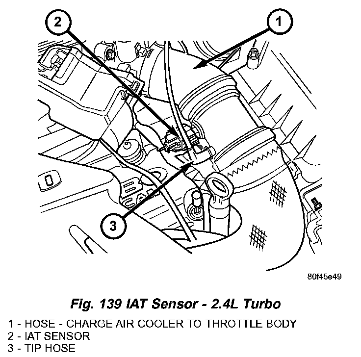
2. Disconnect the inlet air temperature (IAT) sensor connector (Fig. 139).
3. Disconnect the throttle inlet pressure (TIP) hose (Fig. 139).
Fig. 140:
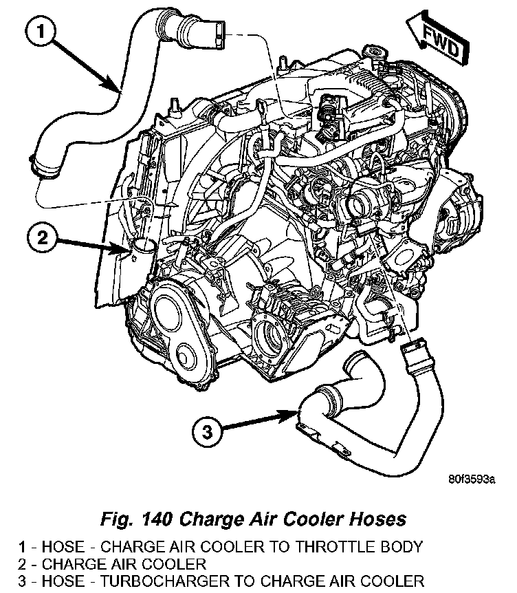
4. Disconnect charge air cooler hose at throttle body (Fig. 139) and (Fig. 140).
5. Disconnect idle air control (IAC) motor and throttle position sensor connectors.
Fig. 141:
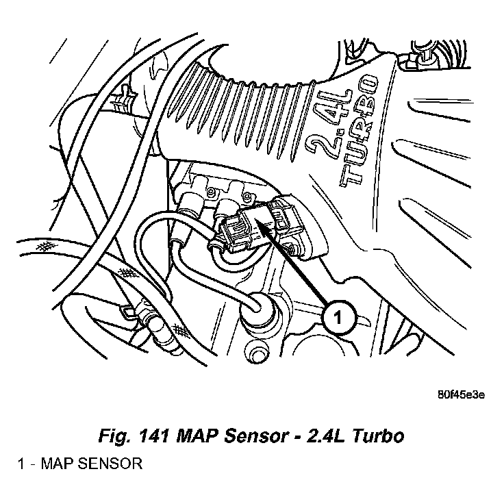
6. Disconnect the MAP sensor connector (Fig. 141).
Fig. 142:
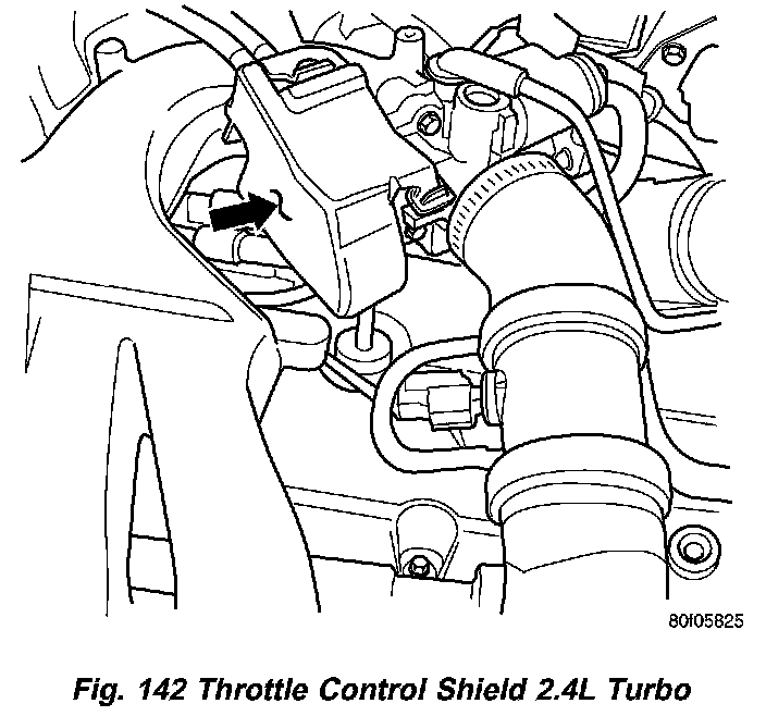
7. Remove the throttle control shield (Fig. 142).
Fig. 143:
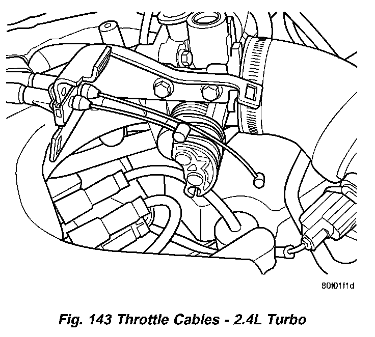
8. Remove the throttle cable from the throttle body lever (Fig. 143).
9. If equipped with speed control, remove speed control cable from the throttle lever by sliding clasp out hole used for throttle cable.
10. Remove the 2 screws for the throttle cable bracket.
Fig. 144:
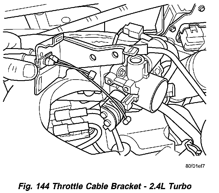
11. Reposition throttle cable bracket (Fig. 144).
12. Disconnect brake booster hose and PCV hose from intake manifold (Fig. 145).
Fig. 145:
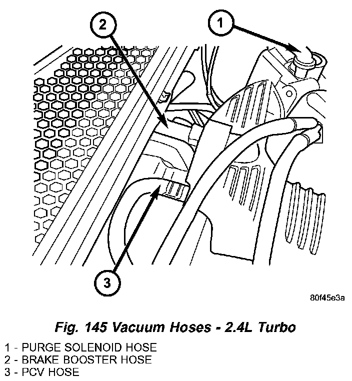
13. Disconnect purge solenoid hose from throttle body (Fig. 145).
Fig. 146:
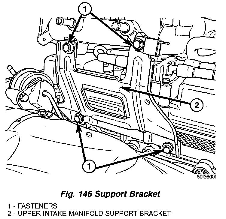
14. Remove upper intake manifold support bracket (Fig. 146).
Fig. 150:

15. Remove upper intake manifold fasteners (Fig. 150).
16. Remove upper intake manifold.
Fig. 138:
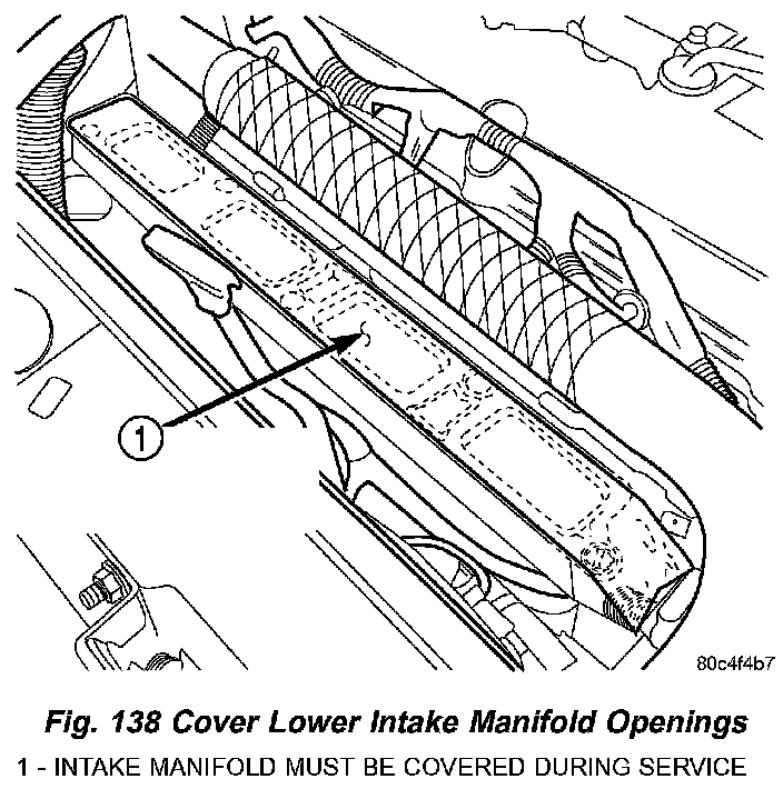
17. If further service is required, cover the lower intake manifold openings to prevent foreign materials from entering the engine (Fig. 138).
INSTALLATION
1. If lower intake manifold was covered during service, remove cover (Fig. 138).
2. Clean all sealing surfaces. Replace upper intake manifold gasket.
3. Position upper intake manifold on lower intake manifold. Tighten upper intake manifold fasteners to 28 Nm (250 in. lbs.) in sequence shown in (Fig. 150).
4. Install upper intake manifold support bracket (Fig. 146). Torque fasteners to 28 Nm (250 in. lbs.).
5. Connect purge solenoid hose to throttle body (Fig. 145).
6. Connect brake booster vacuum hose and PCV hose to intake manifold (Fig. 145).
7. Install the 2 screws for the throttle cable bracket and tighten to 12 Nm (105 in. lbs.).
8. If equipped with speed control, install speed control cable to the throttle lever by sliding clasp in the hole used for throttle cable.
9. Install the throttle cable to the throttle body lever (Fig. 143).
10. Install the throttle control shield (Fig. 142).
11. Connect idle air control (IAC) motor and throttle position sensor connectors.
12. Connect the MAP sensor connector (Fig. 141).
13. Connect charge air cooler hose to throttle body (Fig. 139) and (Fig. 140). Tighten hose clamp to 1.7 Nm (15 in. lbs.).
14. Connect negative battery cable.