Removal and Replacement
REMOVAL - ENGINE ASSEMBLY1) Perform fuel pressure release procedure.
2) Disconnect negative battery cable.
3) Drain the cooling system.
4) Secure the steering wheel in the center position.
5) Evacuate and recover the air conditioning.
6) Disconnect the CCV hose at the left cylinder head cover.
7) Remove the air cleaner cover and housing.
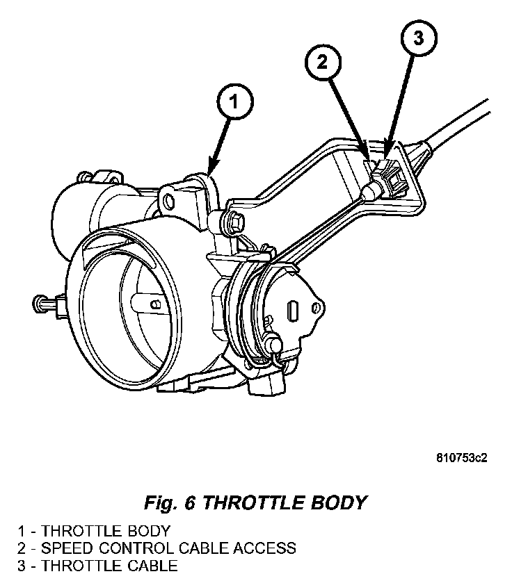
8) Disconnect the throttle and cruise control cable from the throttle, separate the cables from the bracket and set aside (Fig. 6).
9) Disconnect the cruise control and power brake booster vacuum hoses and set aside.
10) Disconnect the upper radiator hose from the thermostat housing and the lower radiator hose from the radiator.
11) Disconnect the heater hoses and coolant reservoir hose from the intake manifold.
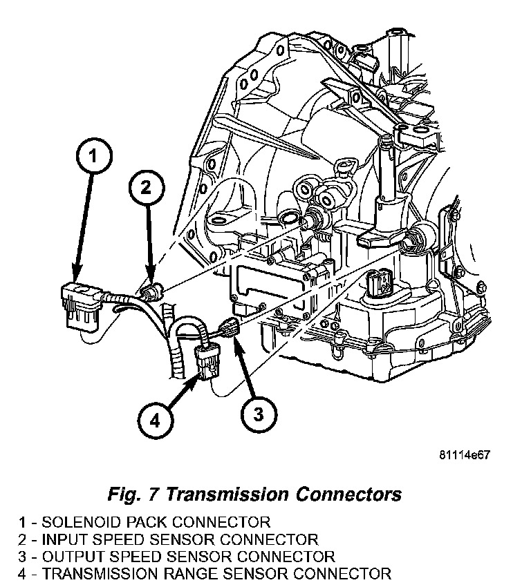
12) Disconnect the transmission controller and transmission sensor wire harness connectors (Fig. 7).
13) Disconnect the brake controller wire harness connector.
14) Disconnect the transmission shift cable, remove the cable from the bracket and set the cable aside.
NOTE: Capture and store any fluid spillage in appropriately marked containers.
15) Disconnect the transmission lines using special tool # 8875.
16) Disconnect the generator electrical connectors.
17) Disconnect the fuel line from fuel rail.
18) Disconnect the EVAP hose from the throttle body
19) Disconnect the throttle position (TP), idle air control (IAC) motor, oxygen (HO2), cam position (CMP), manifold absolute pressure (MAP) and the two engine wiring harness connectors. Free the harness from the cover studs and set harness aside.
20) Disconnect the purge solenoid harness connector.
21) Remove engine wiring harness retainer from left cylinder head cover and oil level indicator tube.
22) Disconnect the A/C electrical connector, and both A/C lines from the compressor. Cover and seal all openings of hoses and compressor.
23) Disconnect the oil pressure sending unit (OPS).
24) Disconnect the coolant hose at the engine oil cooler.
25) Raise and support the vehicle.
26) Remove the front wheels.
27) Remove the front fascia.
28) Disconnect the starter wiring and push pin.
29) Remove the flex plate inspection cover.
30) Rotate the engine at the crankshaft pulley bolt and remove the torque converter bolts.
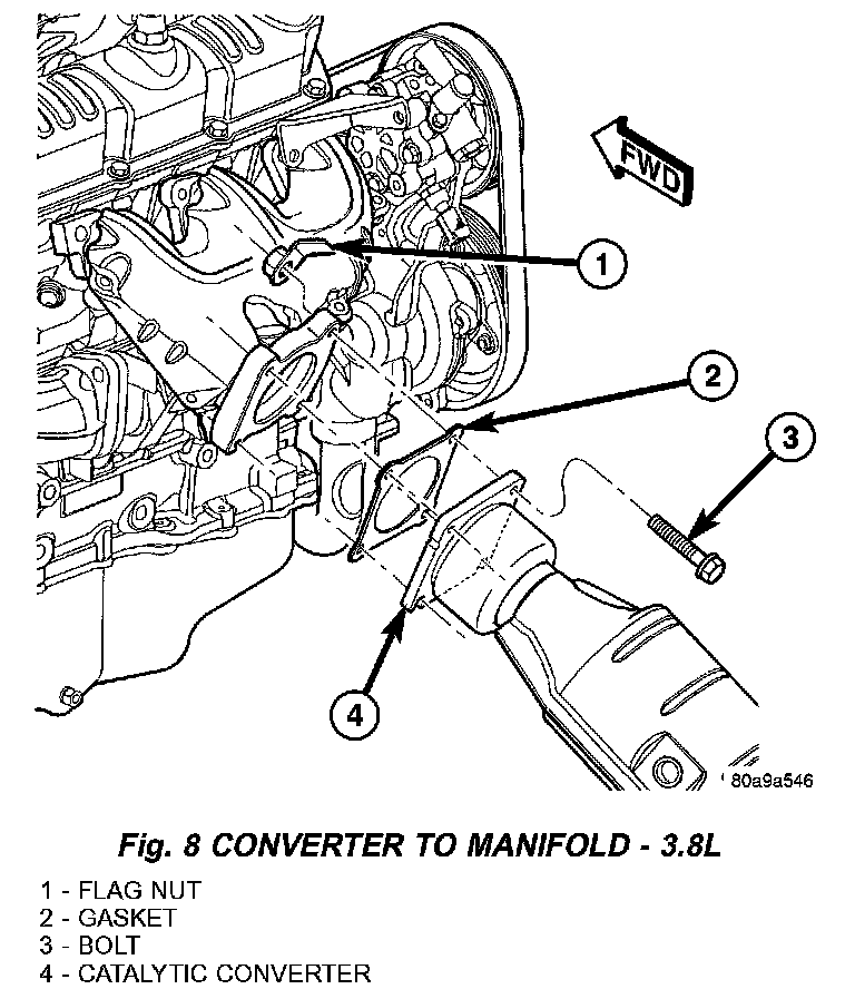
31) Disconnect the rear oxygen sensor and remove the exhaust system (Fig. 8).
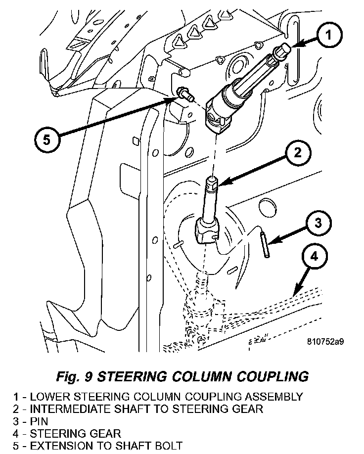
32) Separate the steering column intermediate shaft from the steering gear using special tool # 6831-A (Fig. 9).
33) Disconnect the knock sensor wiring harness connector and remove the crankshaft sensor.
34) Disconnect the in block heater (if equipped).
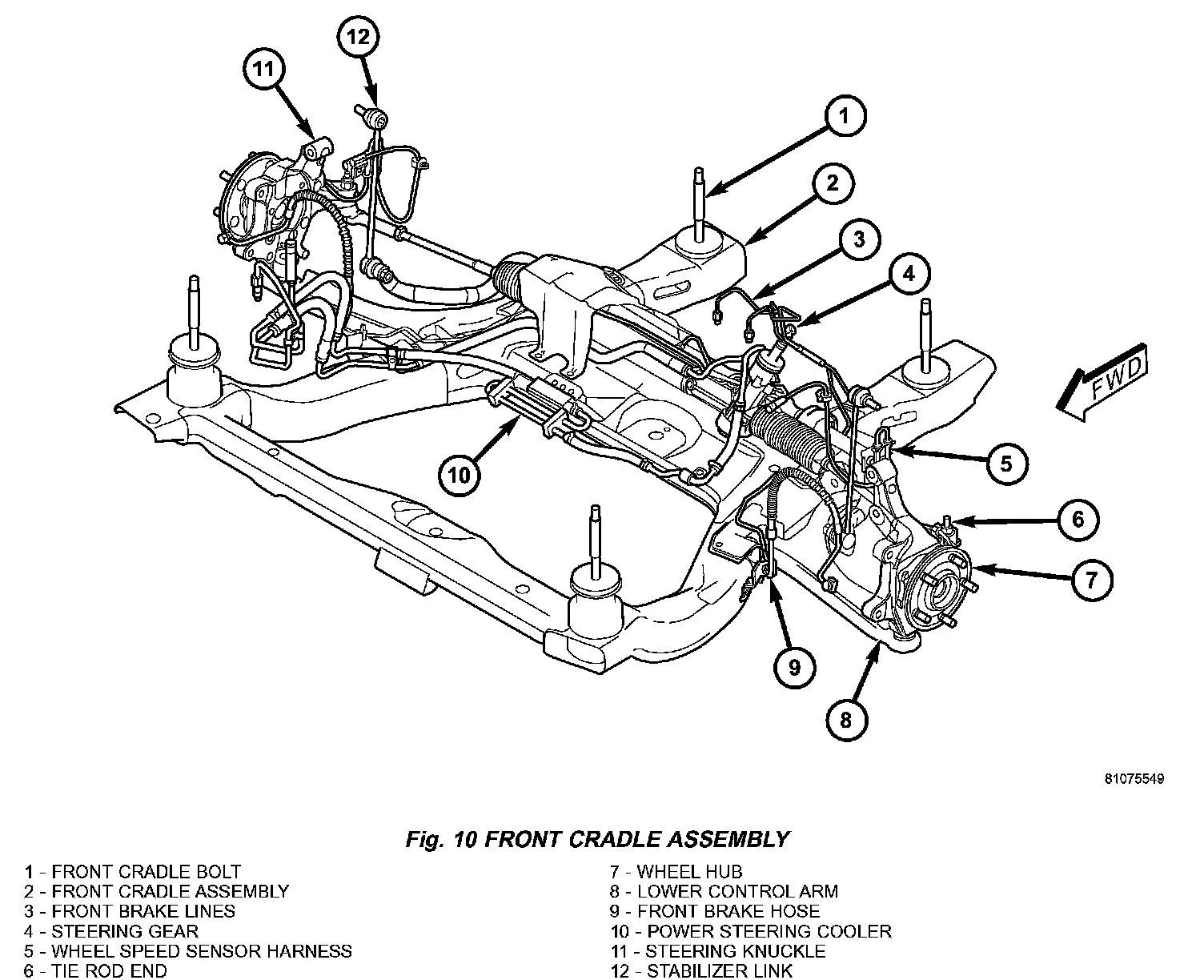
35) Disconnect the left wheel speed sensor and sensor harness push pin from the body and set the harness aside (Fig. 10).
36) Disconnect the left upper stabilizer link (Fig. 10).
37) Disconnect the left strut to steering knuckle bolts and separate the union (Fig. 10).
38) Disconnect the right wheel speed sensor and sensor harness push pin from the body and set the harness aside (Fig. 10).
39) Disconnect the right upper stabilizer link (Fig. 10).
40) Disconnect the right strut to steering knuckle bolts and separate the union (Fig. 10).
41) Disconnect the engine harness ground at the transmission.
42) Disconnect the rear transmission mount from the body.
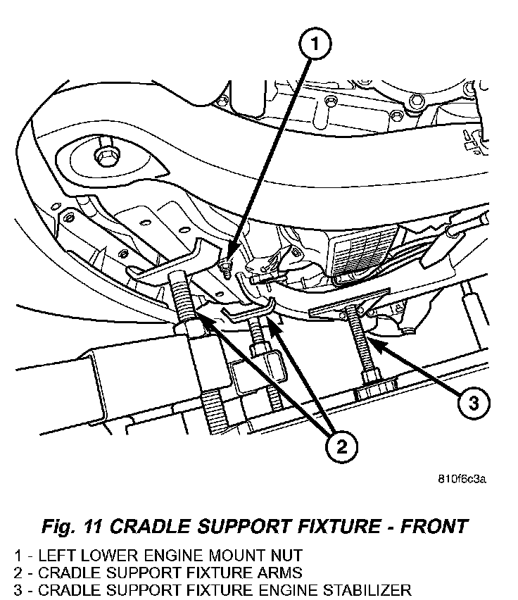
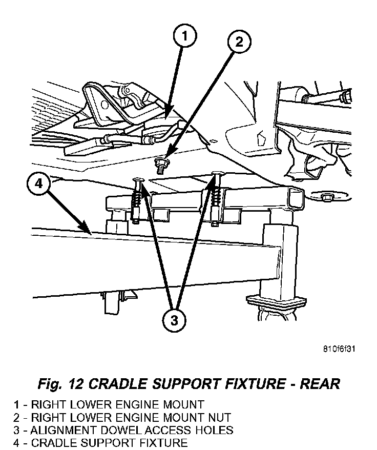
43) Set up and adjust the cradle support fixture arms and dowels, (Fig. 11), (Fig. 12) then paint mark the cradle to body location at all four cradle bolt positions.
CAUTION: DO NOT APPLY the total vehicle weight on the cradle support fixture.
44) Lower the front cradle onto the table (Fig. 11), (Fig. 12) and remove all four front cradle mount bolts.
NOTE: Use a brake pedal prop rod and depress the brake pedal to prevent excessive brake fluid loss when the brake system is open.
45) Disconnect both front brake lines at the brake controller and route aside (Fig. 10).
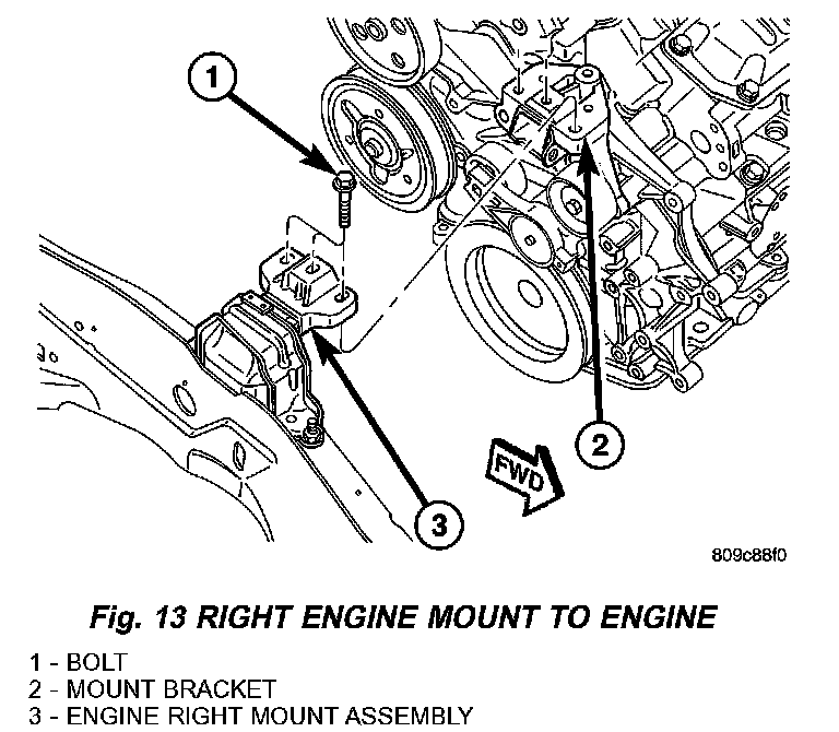
46) Disconnect the right front engine mount (Fig. 13).
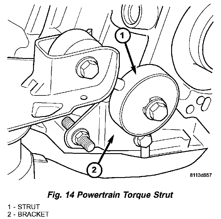
47) Remove the left powertrain torque strut to frame bracket bolt (Fig. 14)
CAUTION: While slowly separating the body from the cradle assembly, constant checks must be performed to assure proper positioning and that no damage occurs during separation.
48) Carefully raise the vehicle off of the engine and cradle assembly.
49) Connect engine lift bracket, special tool # 8534-8 to the left cylinder head and # 8534-7 to the right cylinder head.
50) Separate the engine and transmission from the cradle using the lift brackets.
51) Separate the transmission from the engine.
INSTALLATION - ENGINE ASSEMBLY
CAUTION: While slowly lowering the body to the cradle assembly, constantly check to assure proper positioning and no damage occurs to other components until union is made.
1) Position engine and transmission assembly under vehicle. Slowly lower the vehicle down over the engine and transmission until the cradle is aligned.
2) Install the cradle supporting bolts and tighten to 163 Nm (120 ft. lbs.) (Fig. 10).
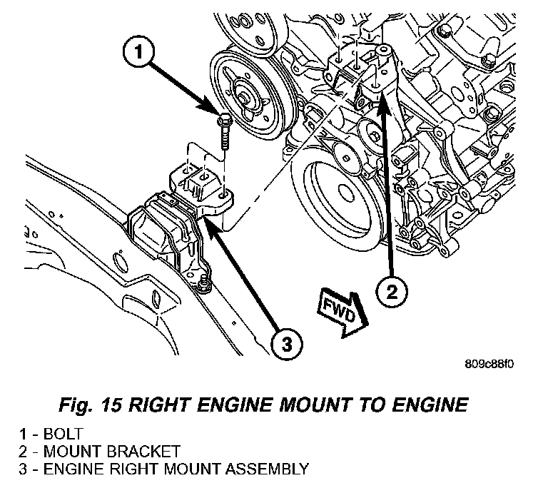
3) Install the right engine mount. tighten the bolts to the timing cover to 54 Nm (40 ft. lbs.), tighten the bolts to the right rail to 68 Nm (50 ft. lbs.). (Fig. 15).
4) Slowly raise the vehicle off of the cradle support.
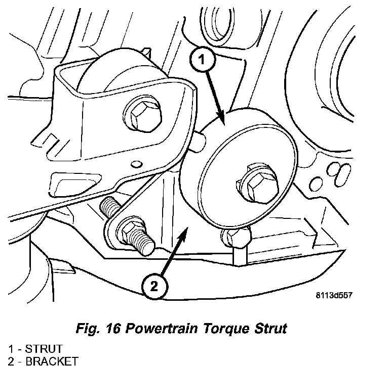
5) Install the rear transmission torque strut and tighten bolts to 54 Nm (40 ft. lbs.) (Fig. 16).
6) Install the engine wiring harness ground strap to transmission case.
7) Connect the left front strut to steering knuckle. Tighten bolts to 81 Nm (60 ft. lbs.) plus 90 degrees.
8) Connect the left stabilizer link. Tighten to 88 Nm (65 ft. lbs.).
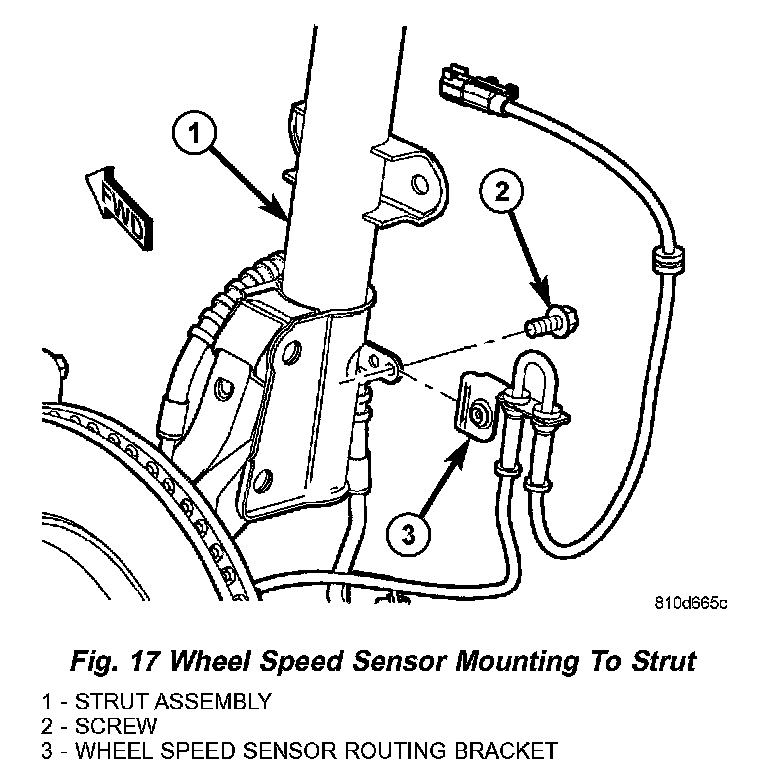
9) Connect the left wheel speed sensor and harness push pin (Fig. 17).
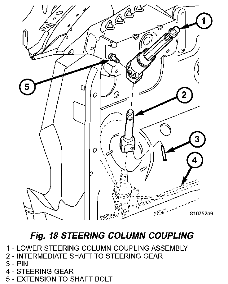
10) Reconnect the steering column intermediate shaft to the steering gear (Fig. 18).
11) Connect the right front strut to steering knuckle. Tighten bolts to 81 Nm (60 ft. lbs.) plus 90 degrees (Fig. 10)
12) Connect the right stabilizer link. Tighten to 88 Nm (65 ft. lbs.) (Fig. 10).
13) Connect the right wheel speed sensor and harness push pin (Fig. 17).
14) Install wheels.
15) Connect the in block heater (if equipped).
16) Connect the knock sensor electrical connector.
17) Install the exhaust system and connect the O2 sensor.
18) Install the torque converter bolts. Tighten the bolts to 88 Nm (65 ft. lbs.).
19) Install the flex plate inspection cover.
20) Connect the starter wiring, route harness and secure with push pin.
21) Install the front fascia.
22) Connect the coolant hose at the engine oil cooler.
23) Connect the oil pressure sending unit (OPS) wiring harness connector.
24) Lower the vehicle.
25) Connect the A/C lines and compressor electrical connector.
26) Route the engine harness to the left cylinder head and attach the purge solenoid.
27) Connect the engine sensor wiring harness connectors.
28) Connect the engine vacuum harnesses.
29) Connect the fuel line to the fuel rail.
30) Connect the generator electrical connectors.
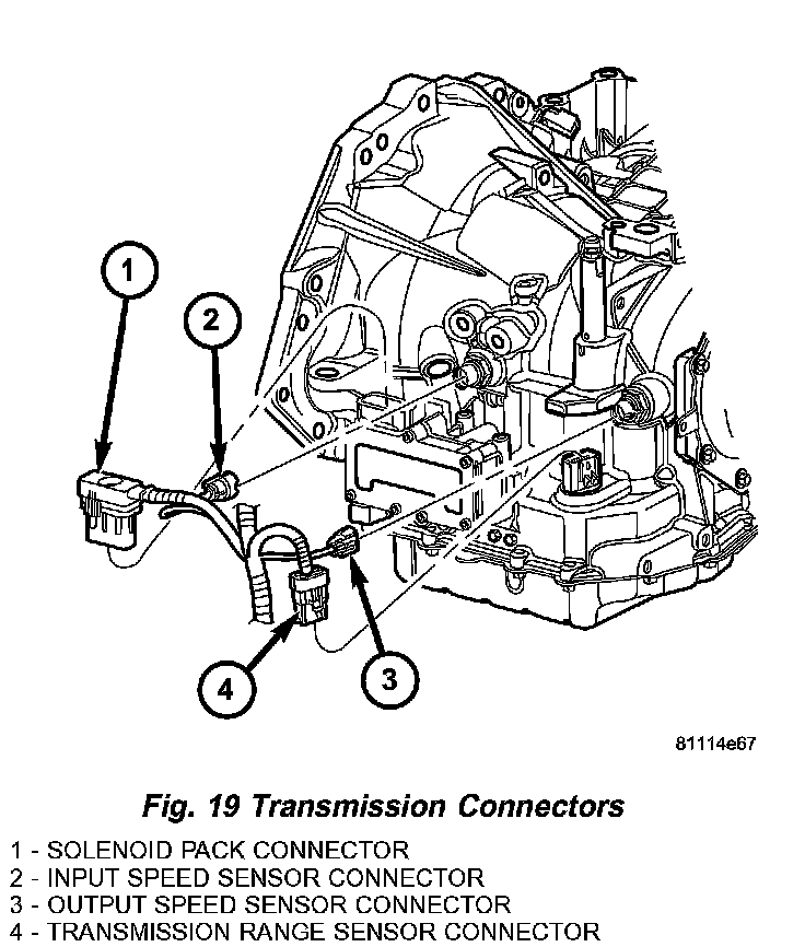
31) Connect the transmission controller, sensor electrical connectors and fluid lines (Fig. 19).
32) Connect the radiator, coolant reservoir and heater hoses.
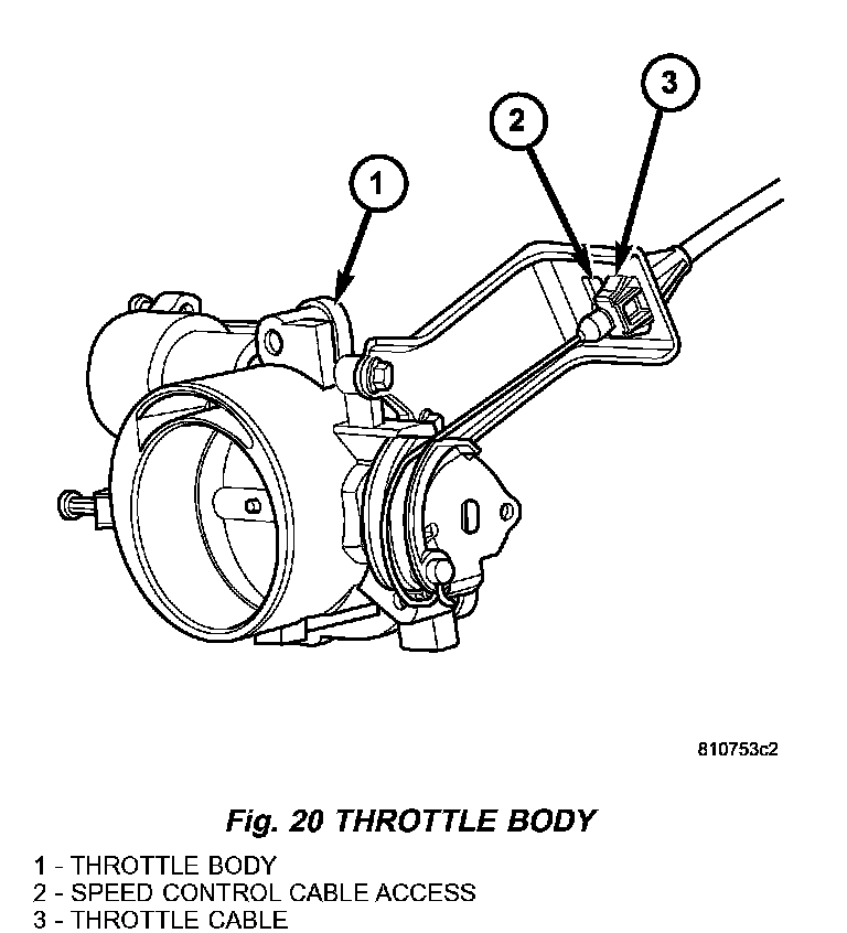
33) Connect the throttle and cruise control cables (Fig. 20).
34) Install the air cleaner housing and connect the CCV hose to the left cylinder head cover.
35) Fill the cooling system.
36) Evacuate and recharge A/C system.
37) Install new oil filter. Fill engine crankcase with proper oil to correct level.
38) Connect negative cable to battery.
39) Fill the cooling system.
40) Bleed the braking system.
41) Start engine and run until operating temperature is reached.