Backing Plate: Service and Repair
PLATE-SUPPORT, BRAKE BACKINGREMOVAL
NOTE: Before proceeding, Refer to Service Precautions.
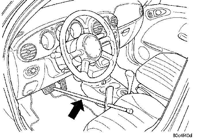
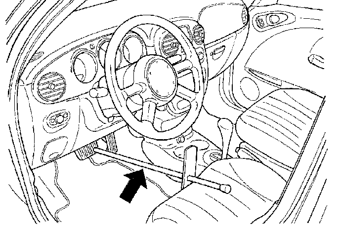
1. Using a brake pedal holding tool as shown, depress the brake pedal past its first one inch of travel and hold it in this position. This will isolate the master cylinder from the brake hydraulic system and will not allow the brake fluid to drain out of the master cylinder reservoir.
2. Raise and support the vehicle.
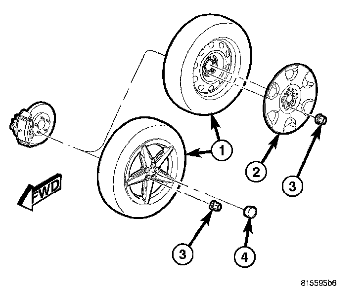
3. Remove the wheel mounting nuts (3), then the tire and wheel assembly.

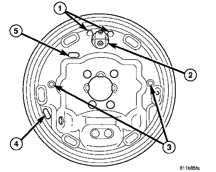
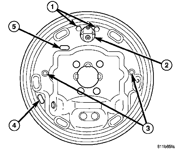
4. On vehicles equipped with antilock brakes, remove the screw (3) securing the antilock brake wheel speed sensor (2) to the support plate. Remove the sensor head from the support plate.
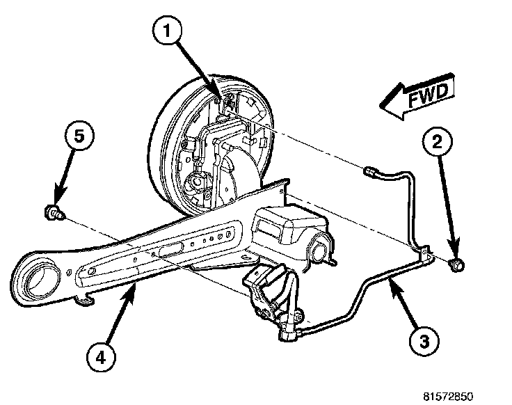
5. Disconnect the brake tube (3) at the wheel cylinder (1).
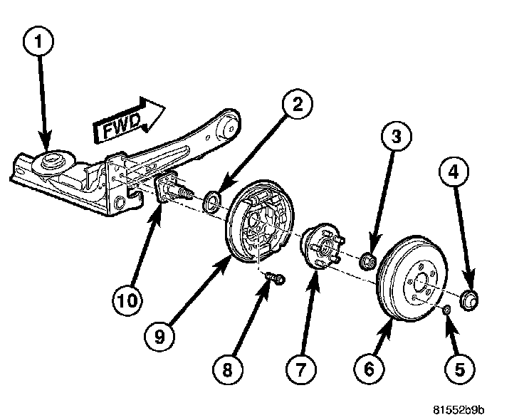
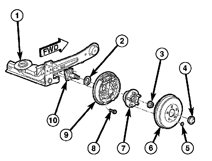
6. Remove any brake drum retaining clips (5), then the drum (6).
7. Remove the dust cap (4) from the rear hub and bearing (7).
8. Remove the hub nut (3) securing the rear hub and bearing (7) to the spindle (10). Slide the hub and bearing off the spindle.
9. Compress the cable return spring, then remove the parking brake cable from the parking brake lever.
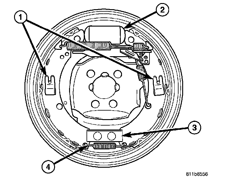
10. Remove the lower return spring (4).
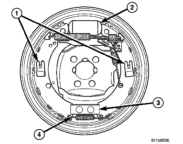
11. Compress and remove both shoe hold-down spring clips (1).
12. Remove both shoes and remaining parts as an assembly from the anchor (3) and the wheel cylinder (2).
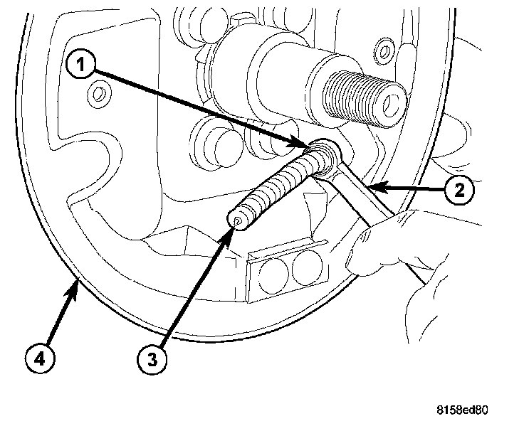
13. Position a 1/2 inch (13 mm) box wrench (2) over the retainer fingers on the end of the parking brake cable housing (1). Compress the cable housing retaining fingers with the wrench, then pull the cable housing out of the support plate (4). Remove the wrench as the parking brake cable retainer is freed from the mounting hole in the brake support plate.
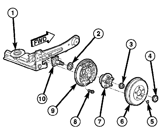
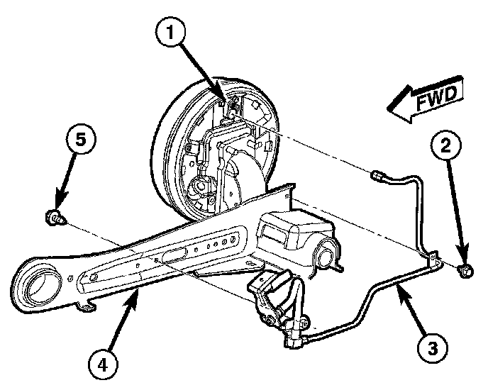
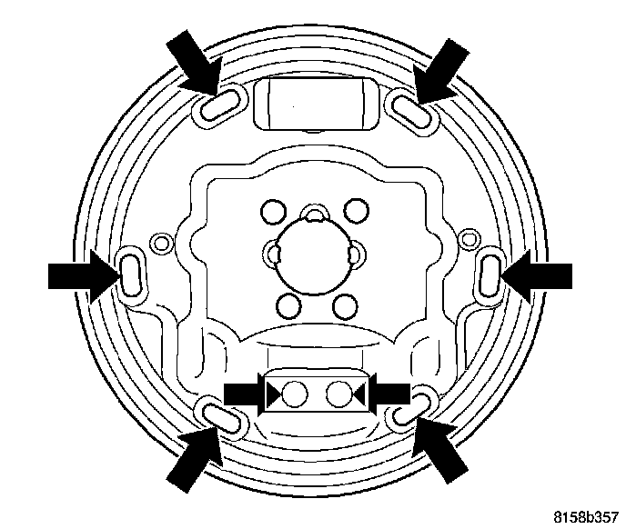
14. Remove the four brake support plate mounting bolts (8). Separate the brake support plate (9) from the spindle (10).
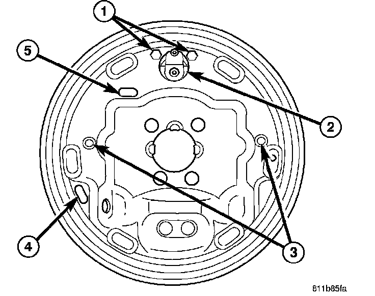
15. Remove the brake wheel cylinder attaching bolts (1).
16. Remove the brake wheel cylinder (2) from the brake support plate.
INSTALLATION
NOTE: When installing wheel cylinder on brake support plate, be sure it is positioned squarely (horizontal) to the brake support plate.
1. Install the wheel cylinder onto brake support plate. Install and tighten the mounting bolts (2) to 13 Nm (115 inch lbs.).

NOTE: When performing the following step, use NEW mounting bolts or clean and apply Mopar Stud & Bearing Mount Adhesive or equivalent to the original mounting bolt threads before reuse.
2. Install the brake support plate (9) and seal (2) on the spindle (10) on the end of the axle (1). Tighten the support plate mounting bolts to 95 Nm (70 ft. lbs.).
3. Insert the parking brake cable into its mounting hole in the brake support plate. Push the cable housing in until the retainer's fingers lock into place.
4. Hand start the brake tube (3) nut to the wheel cylinder (1). Tighten the tube nut to 17 Nm (145 inch lbs.).
5. Lubricate shoe contact areas on support plate and anchor using Mopar Brake Lubricant or equivalent.
NOTE: Inspect the brake shoes before installation.
6. Install the pre-assembled brake shoe assembly over the wheel cylinder (2) and the anchor (3) on the brake support plate.
7. Install both shoe hold-down pins (3) from the rear, through the support plate and shoes.
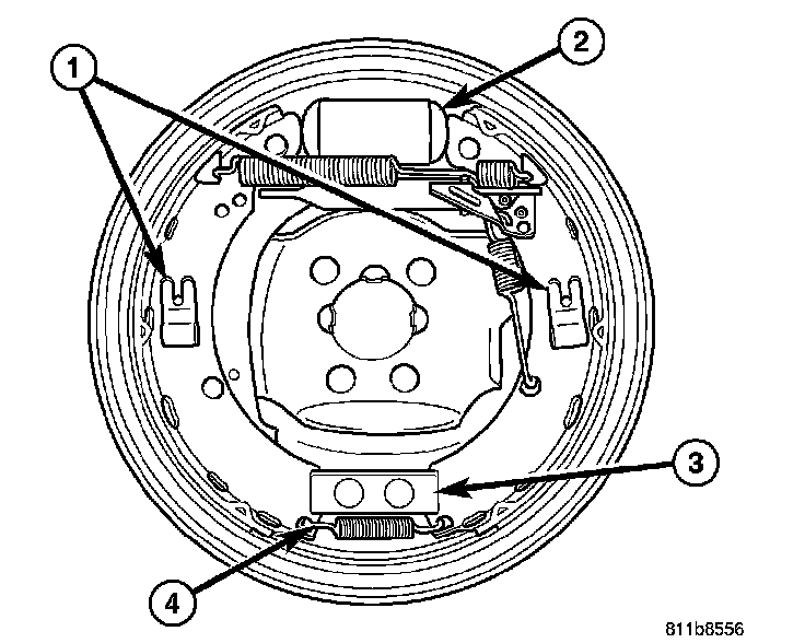
8. Compress and install the shoe hold-down spring clips (1) on the pins.
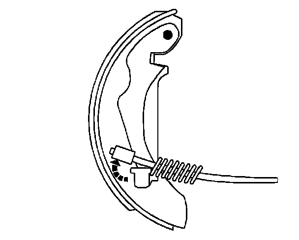
9. Install the lower return spring (4).

10. Compress the parking brake cable return spring, then install the cable on the parking brake lever. Release the spring guiding it beneath the retaining tab on the lever.
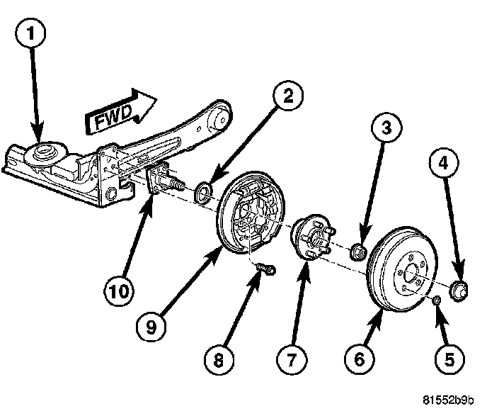
11. Slide the hub and bearing (7) onto the spindle.
12. Install a NEW hub nut (3) on the spindle. Tighten the nut to 217 Nm (160 ft. lbs.).
13. Install the hub and bearing dust cap (4).
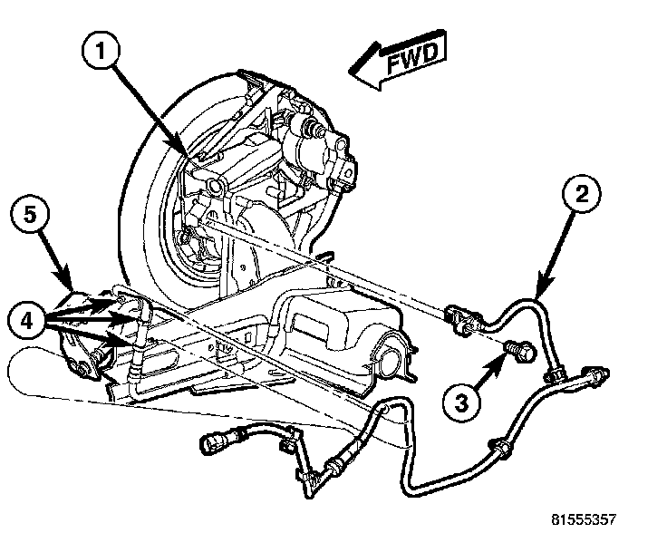
14. If equipped with ABS, Install the wheel speed sensor (2) head into the rear of the support plate. Install and tighten the sensor mounting screw (3) to 12 Nm (105 inch lbs.).
15. Adjust the brake shoes to the drum diameter using a brake shoe gauge.
16. Install the brake drum (6).
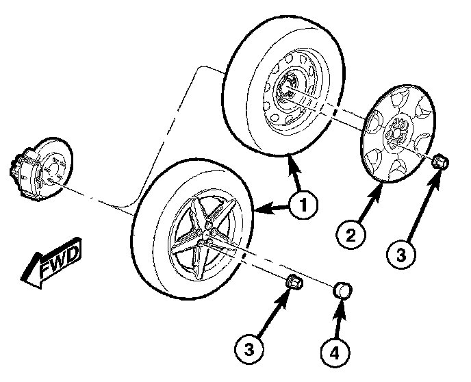
17. Install the tire and wheel assembly (1). Install and tighten the wheel mounting nuts (3) to 135 Nm (100 ft. lbs.).
18. Slowly rotate the rear wheel and verify that the brake drum lightly drags on the shoes.
19. Lower the vehicle.
20. Remove the brake pedal holding tool.
21. Bleed the affected wheel cylinder as necessary.
22. Road test the vehicle to ensure proper brake operation.