Assembly (Part 2)
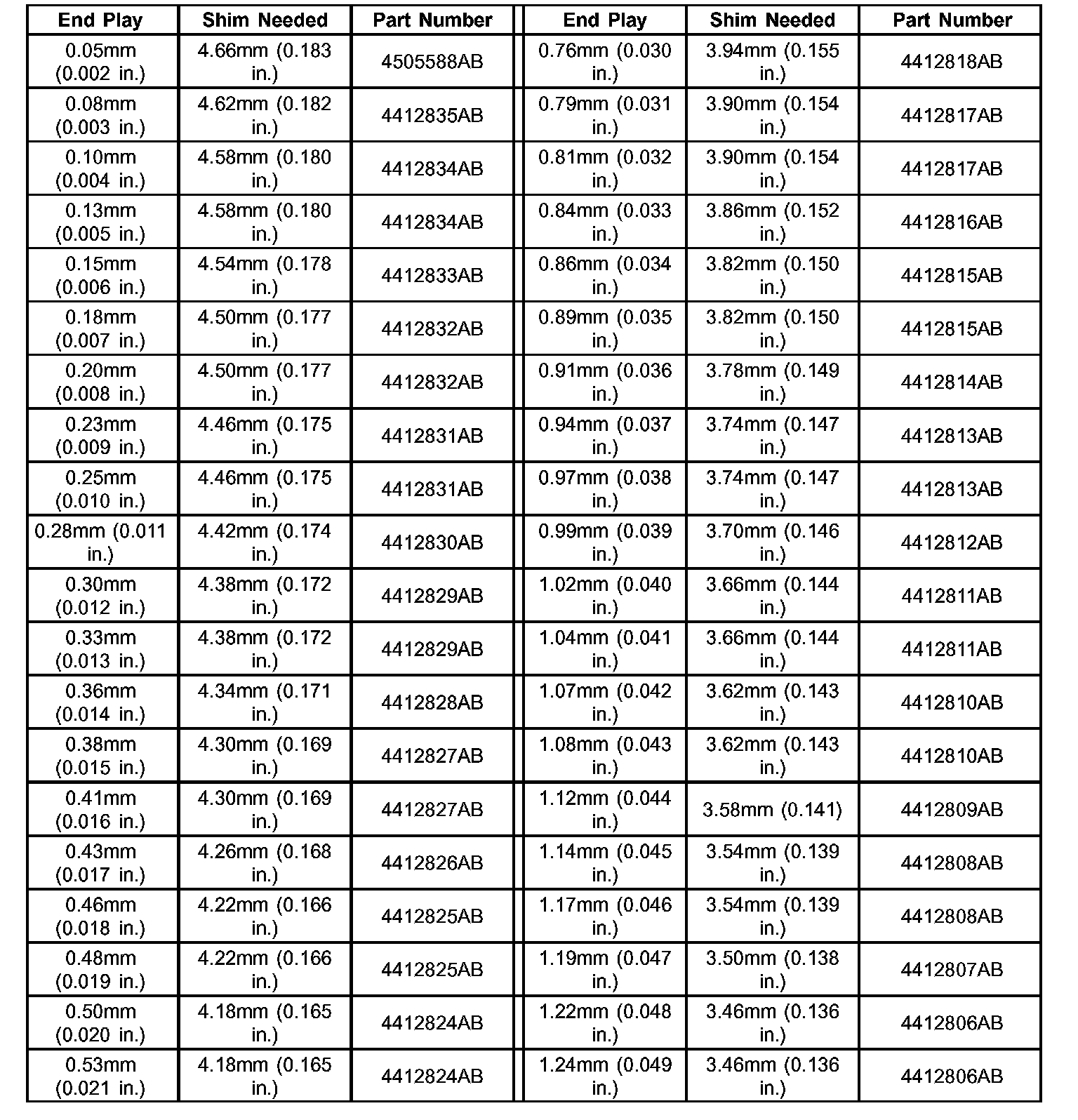
Assembly (Part 2)TRANSFER SHAFT BEARING SHIM CHART (1):
TRANSFER SHAFT BEARING SHIM CHART (2):
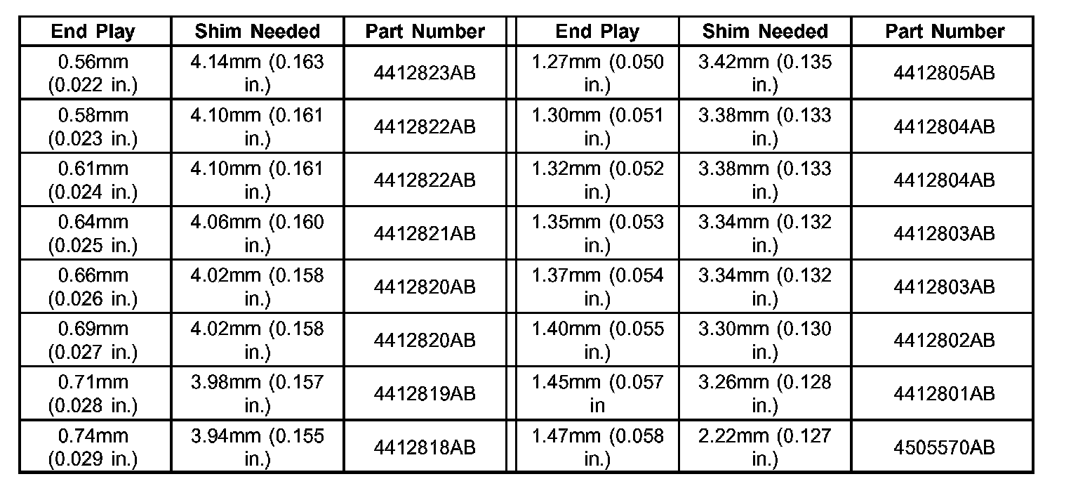
TRANSFER SHAFT BEARING SHIM CHART
Fig. 143 Install Transfer Shaft Gear:
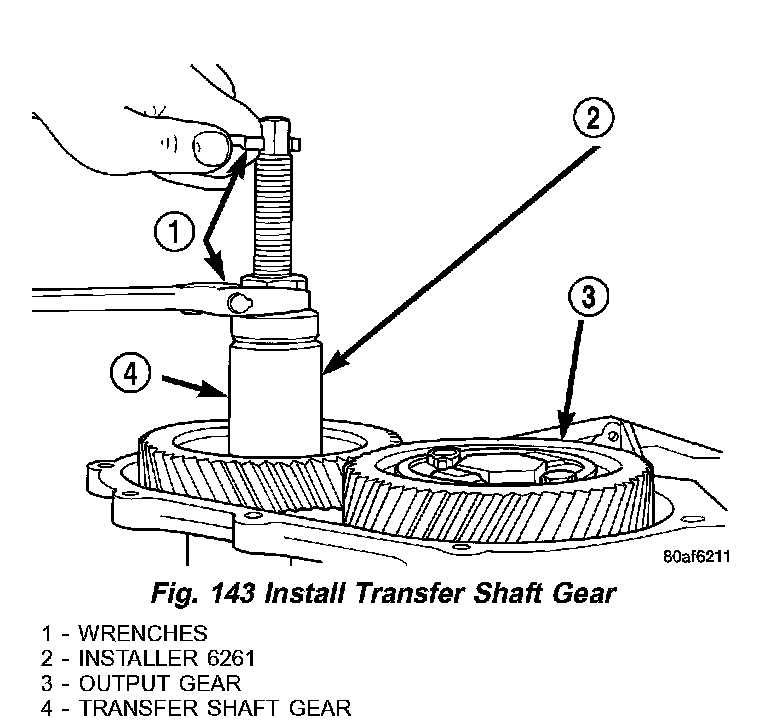
34. Install the transfer shaft gear (4) (Fig. 143) using Installer 6261 (2).
CAUTION: Install a NEW retaining nut, as the original nut MUST NOT be reused.
35. Install the new retaining nut and washer.
Fig. 144 Tighten Transfer Gear Nut to 271 Nm (200 ft. lbs.):
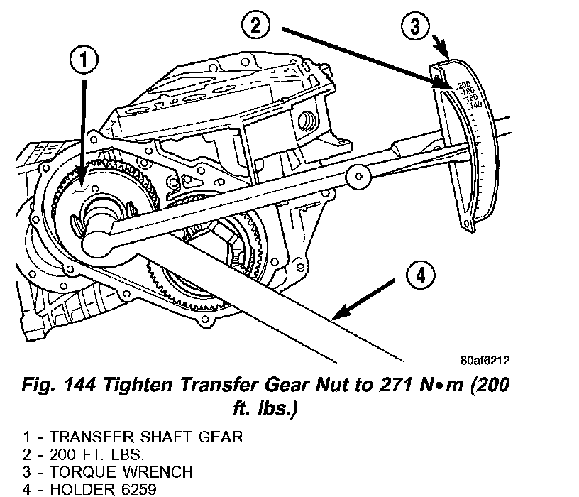
36. Using Holder 6259 (4) (Fig. 144), torque transfer gear retaining nut to 271 Nm (200 ft. lbs.).
37. Measure transfer shaft end play. Transfer shaft end play should be within 0.05 - 0.10 nun (0.002 - 0.004 inch). If the end play is too high, install a 0.04 mm (0.0016 inch) thicker shim. If the end play is too low, install a 0.04 mm (0.0016 inch) thinner shim. Repeat until 0.05 - 0.10 mm (0.002 - 0.004 inch) end play is obtained.
Fig. 145 Install Rear Cover:
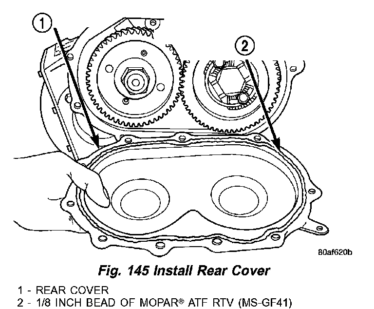
38. Install a bead of Mopar� ATF RTV (MS-GF4 1) (2) (Fig. 145) to transfer gear cover (1).
Fig. 146 Install Rear Cover Bolts:
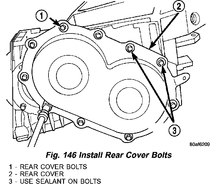
39. Use sealant on bolts (3) (Fig. 146), install transfer gear cover-to-case bolts (1) and torque to 20 Nm (175 inch lbs.) torque.
Fig. 147 Install Low/Reverse Clutch Pack:
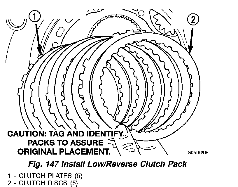
40. Install low/reverse clutch pack (1,2) (Fig. 147). Leave uppermost disc out until snap ring is installed.
Fig. 148 Install Low/Reverse Reaction Plate Snap Ring:
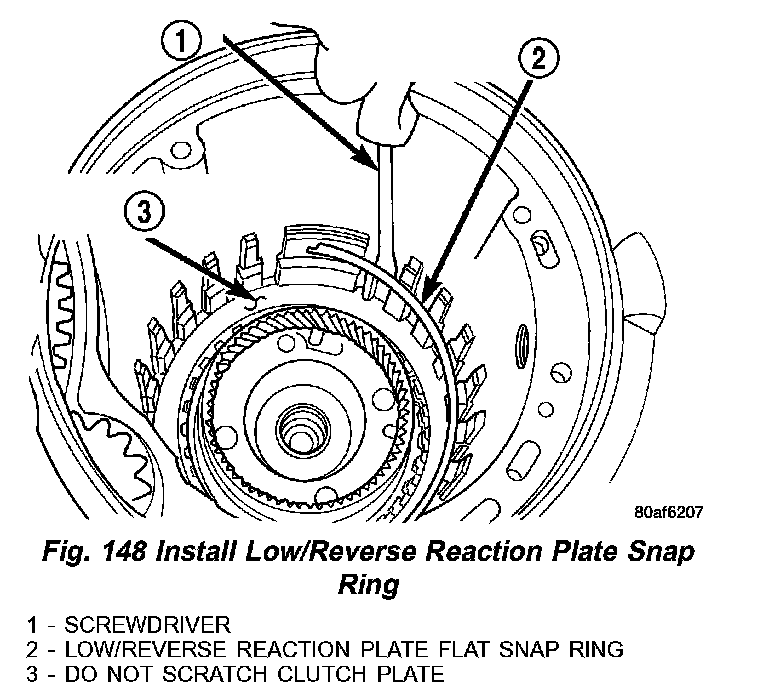
41. Install low/reverse reaction plate flat snap ring (2) (Fig. 148) insure you do not scratch clutch plate (3).
Fig. 149 Install One Disc:
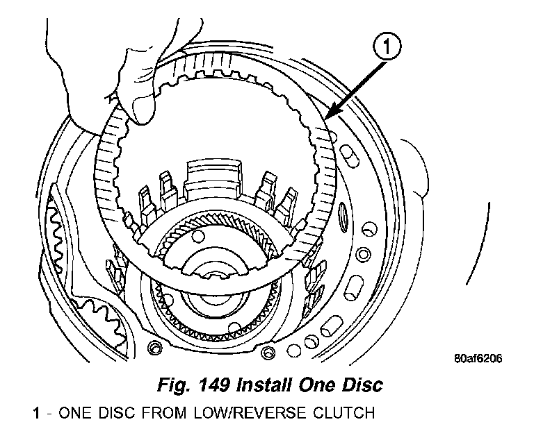
42. Install remaining low/reverse clutch disc (1) (Fig. 149).
Fig. 150 Install Low/Reverse Reaction Plate:
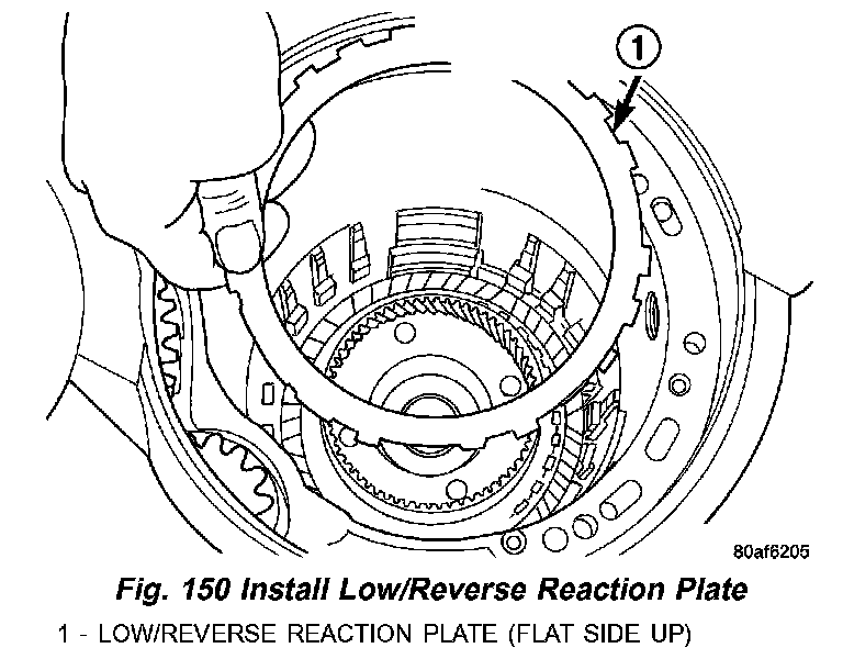
43. Install low/reverse reaction plate with flat side up (1) (Fig. 150).
Fig. 151 Tapered Snap Ring Instructions:
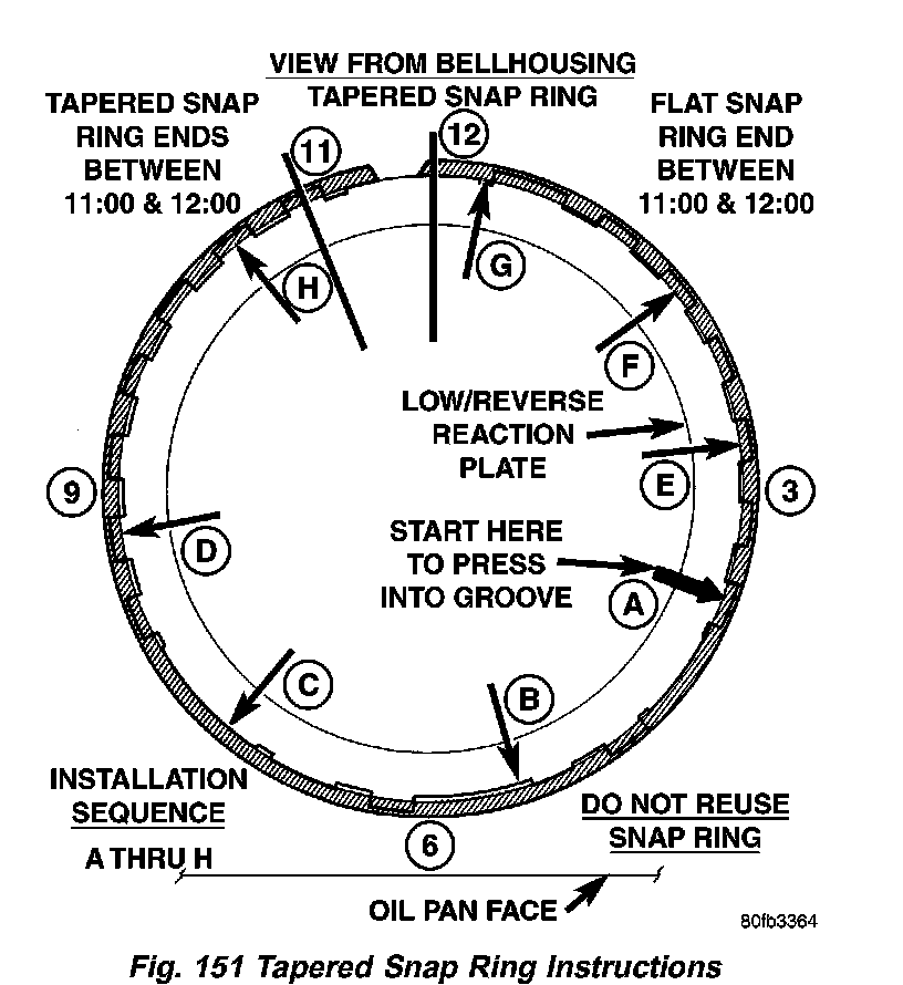
44. Use as a reference while installing tapered snap ring (Fig. 151).
Fig. 152 Snap Ring Installed:

45. Install tapered snap ring (with tapered side up) (2) (Fig. 152).
Fig. 153 Check Low/Reverse Clutch Clearance:
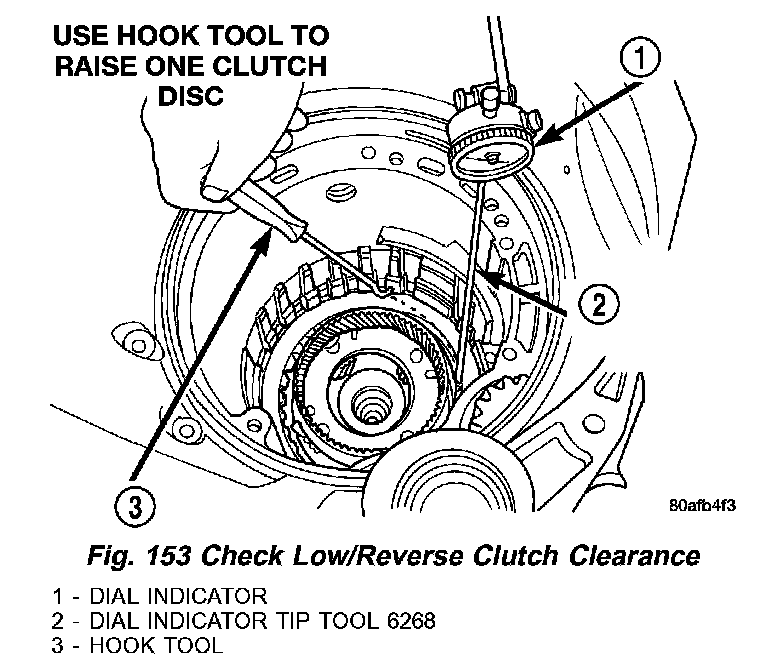
46. Set up dial indicator (1) (Fig. 153) to measure low/reverse clutch clearance. Press down on clutch pack with finger and zero dial indicator. Low/Reverse clutch pack clearance is 0.89 - 1.47 mm (0.035 - 0.058 inch). Set up indicator and record measurement in four places. Take average of readings and select the proper low/reverse reaction plate to achieve specifications.
LOW/REVERSE REACTION PLATE CHART:
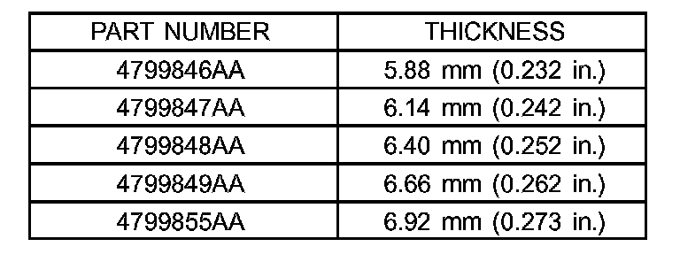
LOW/REVERSE REACTION PLATE CHART
Fig. 154 Install 2/4 Clutch Pack:
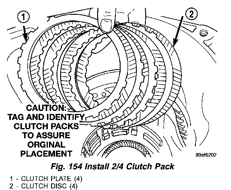
47. Install 2/4 clutch pack (1, 2) (Fig. 154).
NOTE: The 2/4 Clutch Piston has bonded seals which are not individually serviceable. Seal replacement requires replacement of the piston assembly.
Fig. 155 Proper Orientation of 2/4 Clutch Retainer and Spring:
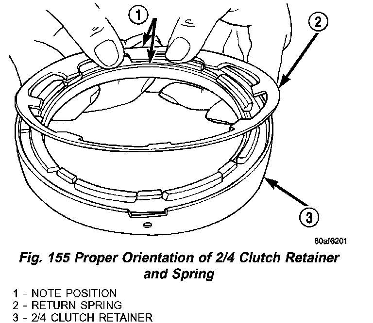
48. Orient 2/4 clutch return spring to retainer (3) (Fig. 155).
Fig. 156 2/4 Clutch Retainer:
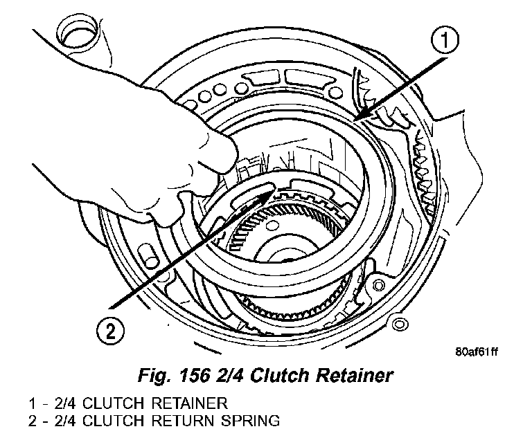
49. Install 2/4 clutch retainer to transaxle (1, 2) (Fig. 156).
Fig. 157 Install 2/4 Clutch Retainer Snap Ring:
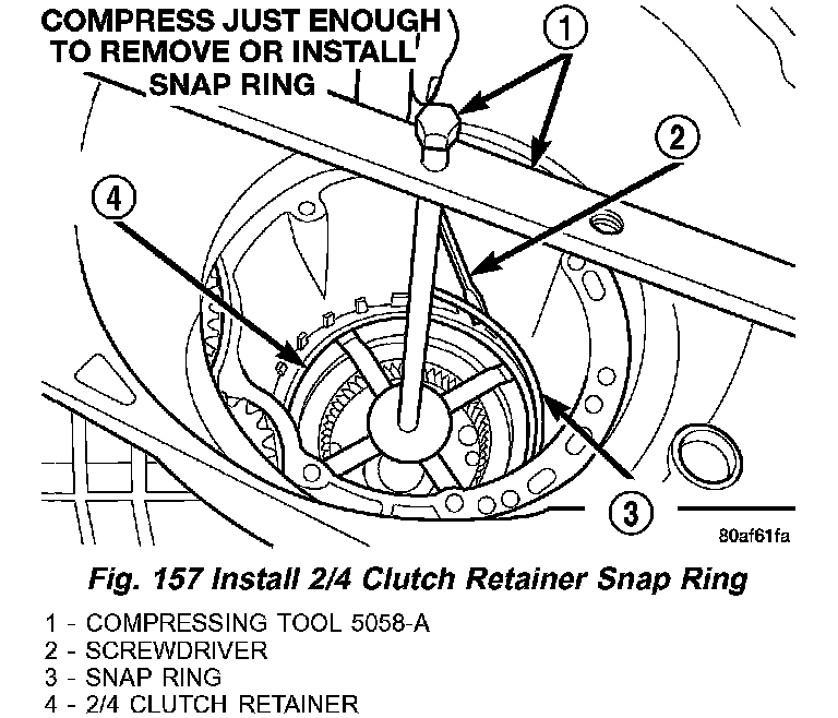
50. Using Compressing Tool 5058-A (1) (Fig. 157), compress 2/4 clutch return spring just enough to install snap ring (3).
51. Install snap ring.
Fig. 158 Check 2/4 Clutch Clearance:
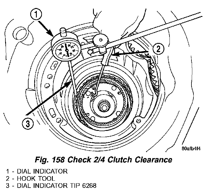
52. Set up dial indicator (1) (Fig. 158) and measure 2/4 clutch clearance. Press down on clutch pack with finger and zero dial indicator. 2/4 clutch pack clearance is 0.76 - 2.64 mm (0.030 - 0.104 inch). Set up indicator and record measurement in four (4) places. Take average of readings. If clearance is outside this range, the clutch is assembled improperly. There is no adjustment for 2/4 clutch clearance.
Fig. 159 Number 7 Bearing:
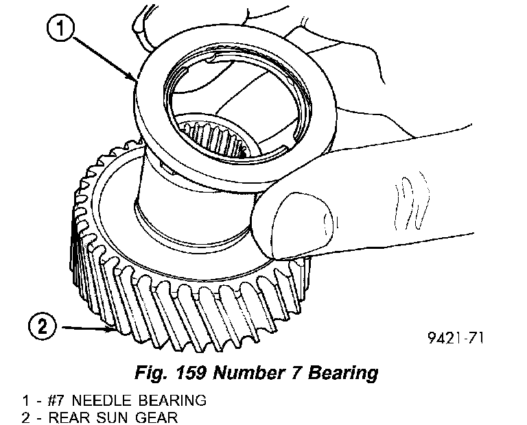
NOTE: The number seven needle (1) (Fig. 159) bearing has three anti-reversal tabs and is common with the number five and number two position. The orientation should allow the bearing to seat flat against the rear sun gear. A small amount of petrolatum can be used to hold the bearing to the rear sun gear (2).
Fig. 160 Install Rear Sun Gear and #7 Needle Bearing:
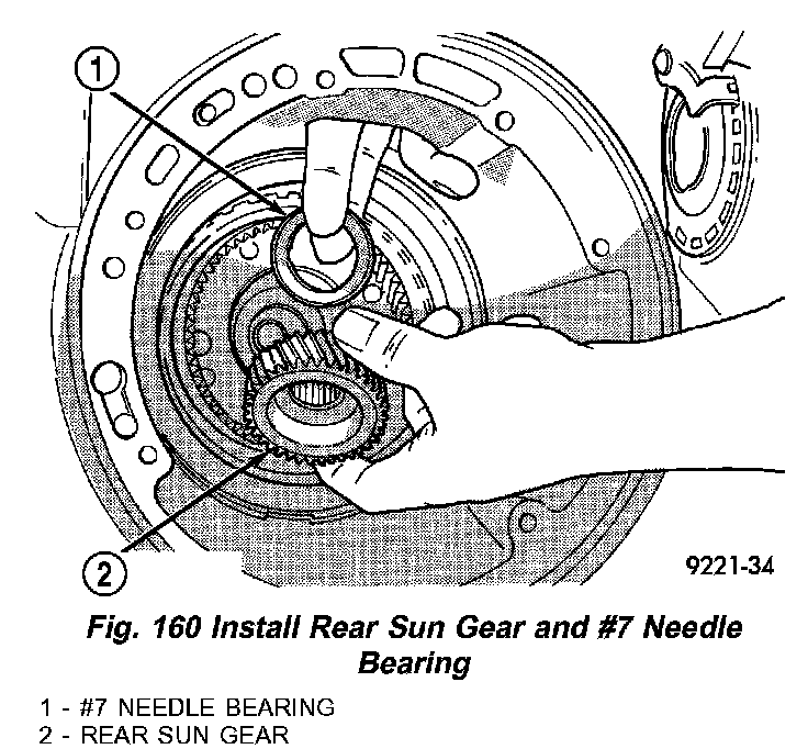
53. Install rear sun gear (2) (Fig. 160) and #7 needle bearing (1).
Fig. 161 Install Front Carrier and Rear Annulus Assembly:
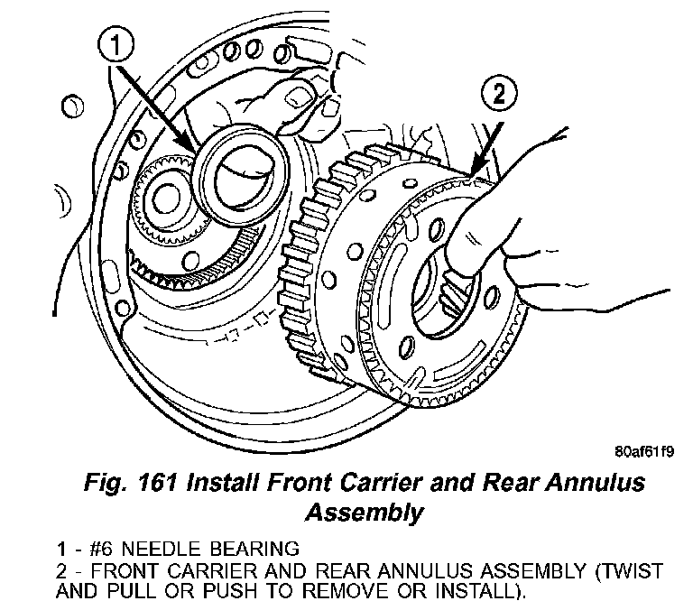
54. Install front carrier/rear annulus assembly (2) (Fig. 161) and #6 needle bearing (1).
Fig. 162 Install Front Sun Gear Assembly:
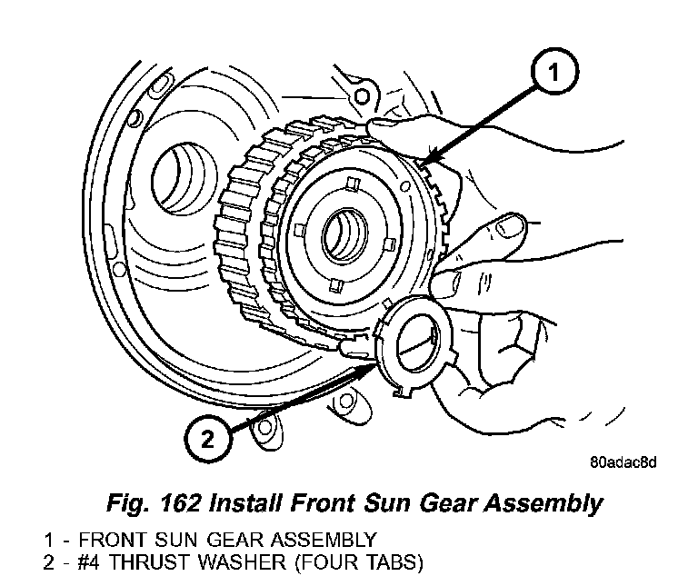
55. Install front sun gear assembly (1) (Fig. 162) and #4 thrust washer (2).
Fig. 163 Select Thinnest No. 4 Thrust Plate:
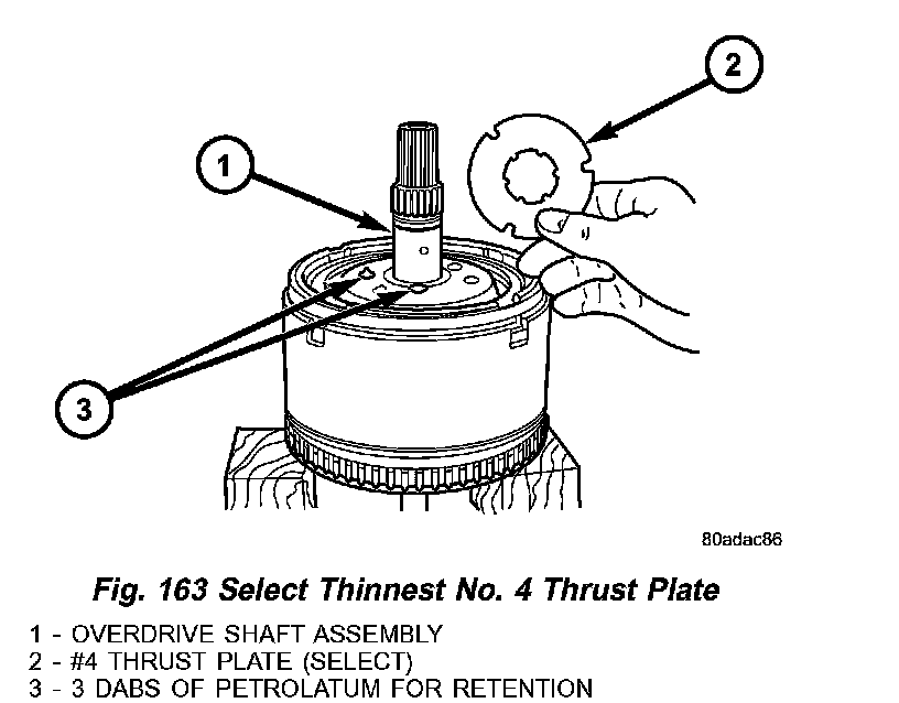
56. Select the thinnest #4 thrust plate thickness (2) (Fig. 163) and install to input clutch assembly Use petrolatum to retain (3).
Fig. 164 View Through Input Speed Sensor Hole:
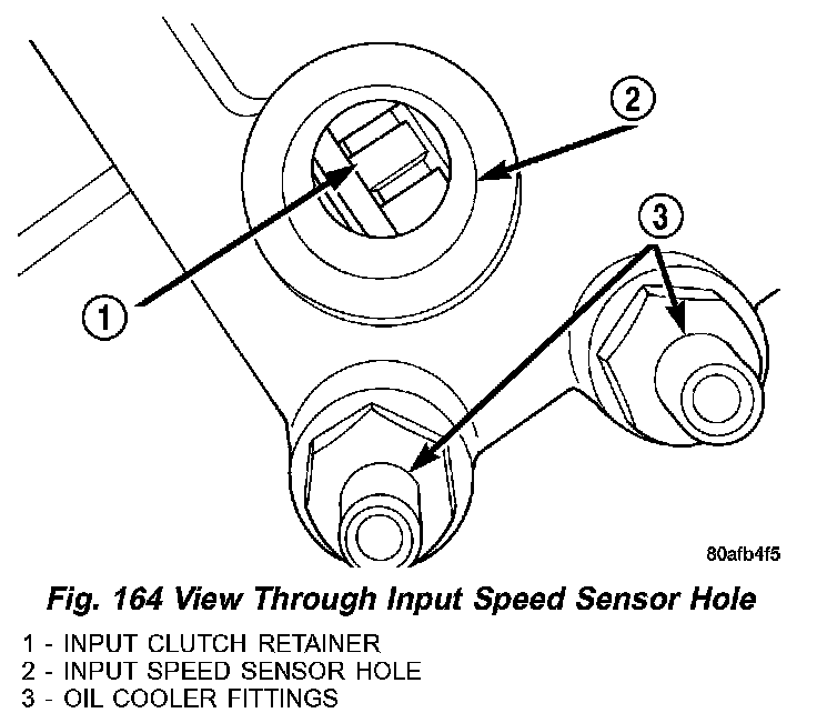
57. Install input clutch assembly into position and verify that it is completely seated by viewing through input speed sensor hole (2) (Fig. 164). If view through input speed sensor hole is not as shown in the below view, the input clutch assembly is not seated properly.
Fig. 165 Remove Oil Pump O-Ring:
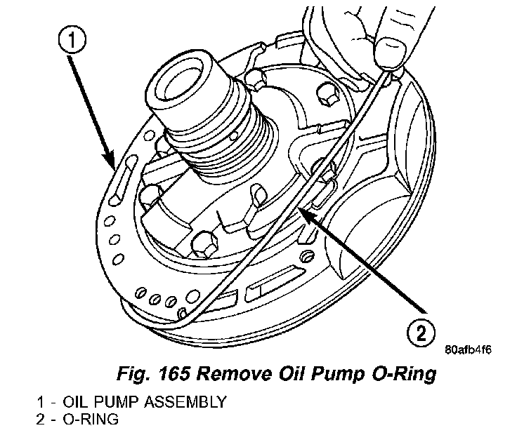
58. Remove oil pump O-ring (2) (Fig. 165). Be sure to reinstall oil pump O-ring after selecting the proper #4 thrust plate.
59. Install pump and gasket to transmission. Install and torque bolts.
Fig. 166 Measure Input Shaft End Play Using End Play Set 8266:
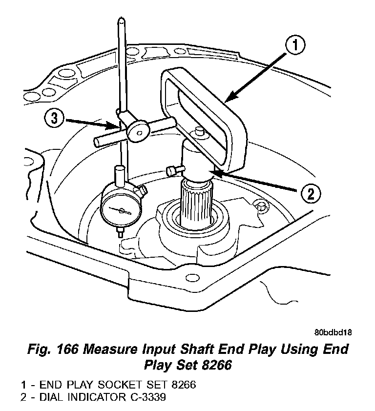
60. Set up input shaft for measurement with Indicator Set C3339 (2) and End Play Set 8266 (1) (Fig. 166).
61. Measure the input shaft end play with the transaxle in the vertical position. Input shaft end play must be within 0.005 to 0.025 inch. For example, if end play reading is 0.055 inch, select No. 4 Thrust Plate which is 0.071 to 0.074 thick. This should provide an input shaft end play reading of 0.020 inch which is within specifications.
NO. 4 THRUST PLATE CHART:
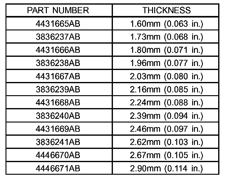
62. Refer to the No. 4 thrust plate chart NO. 4 THRUST PLATE CHART to select the proper No. 4 thrust plate.
Fig. 167 Install Input Clutch Assembly:
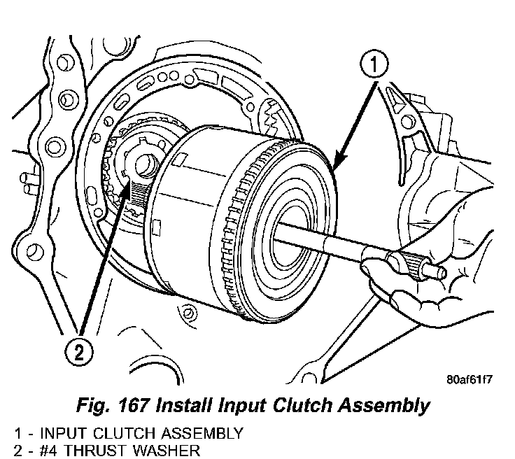
63. Install input clutch assembly (1) (Fig. 167).
Fig. 168 Install Caged Needle Bearing:
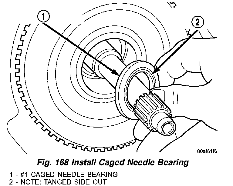
64. Install #1 caged needle bearing (1) (Fig. 168) note: tanged side out (2).
CAUTION: The cooler bypass valve must be replaced if transaxle failure has occurred. Do not attempt to reuse or clean old valve.
Fig. 169 Install Cooler Bypass Valve:
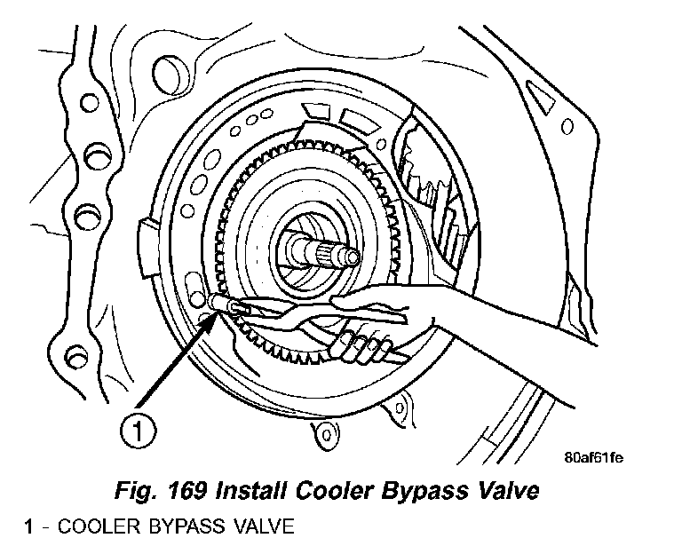
65. Install cooler bypass valve (1) (Fig. 169) with O-ring end towards rear of case.
Fig. 170 Install Oil Pump Gasket:
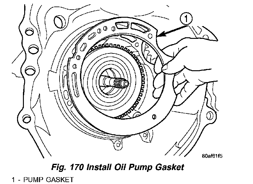
66. Install oil pump gasket (1) (Fig. 170).
Fig. 171 Install Oil Pump:
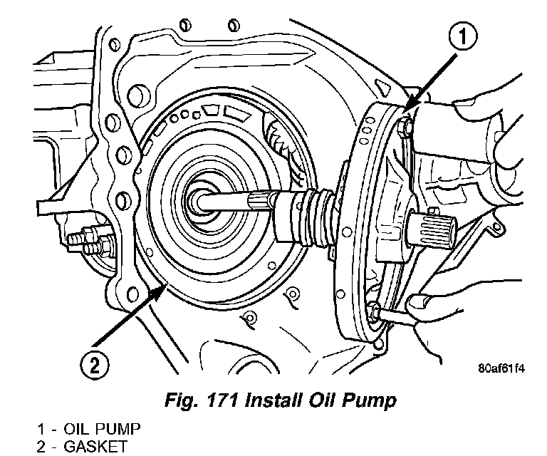
67. Install oil pump (1) (Fig. 171).
Fig. 172 Install Pump-to-Case Bolts:
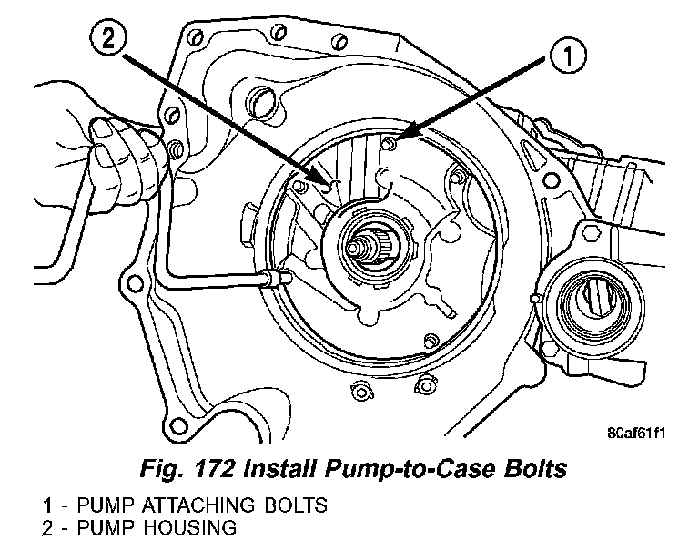
68. Install oil pump-to-case bolts (1) (Fig. 172) and torque to 27 Nm (20 ft. lbs.).
Fig. 173 Install Low/Reverse Accumulator:
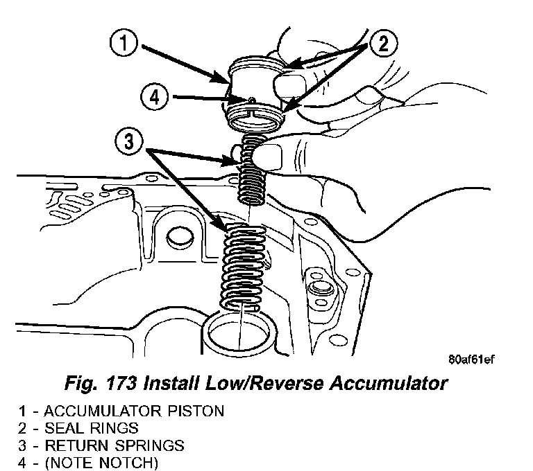
69. Install low/reverse accumulator (1) (Fig. 173).
Fig. 174 Install Low/Reverse Accumulator Plug (Cover):
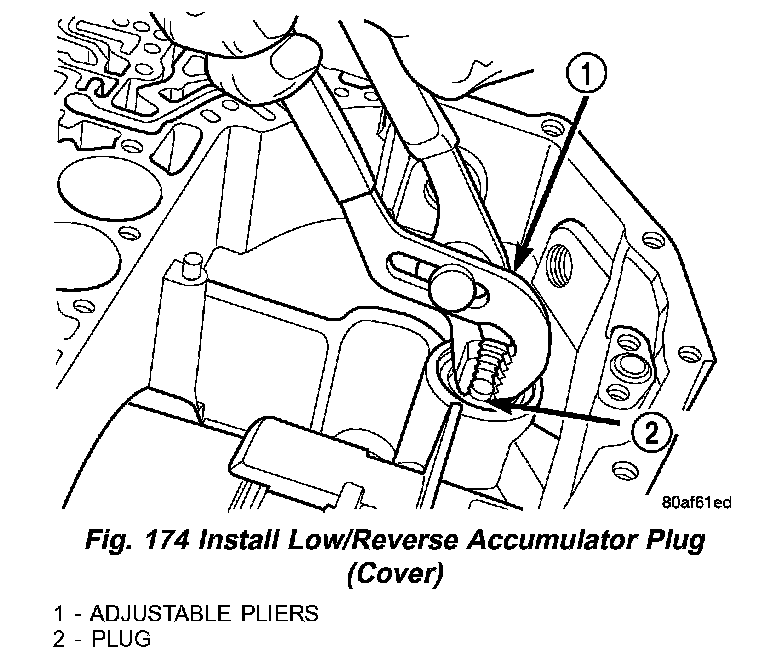
70. Install low/reverse accumulator plug (2) (Fig. 174).
Fig. 175 Install Low/Reverse Accumulator Snap Ring:
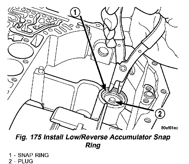
71. Install low/reverse accumulator snap ring (1) (Fig. 175).
NOTE: Depending on engine application, some accumulators will have two springs, and others will have one spring. The springs are color-coded for application and year.
Fig. 176 Underdrive and Overdrive Accumulators:
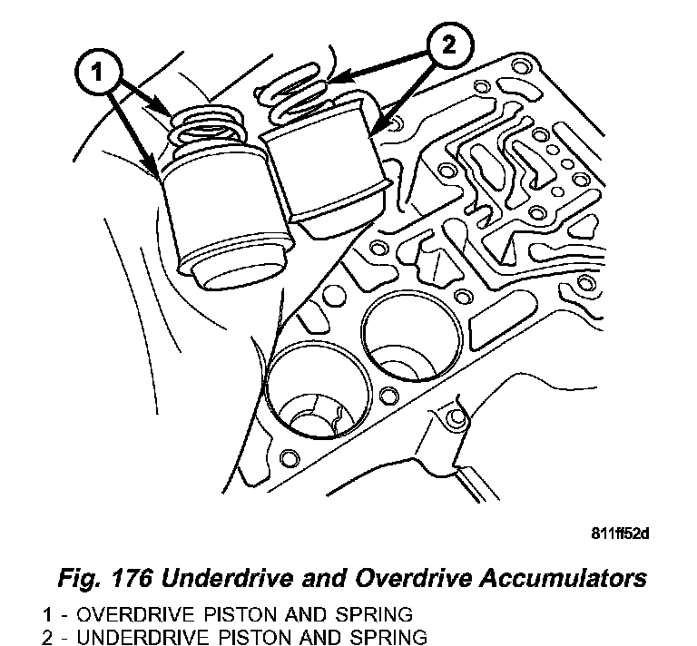
72. Install underdrive and overdrive accumulators (1, 2) (Fig. 176).
Fig. 177 Install Valve Body:
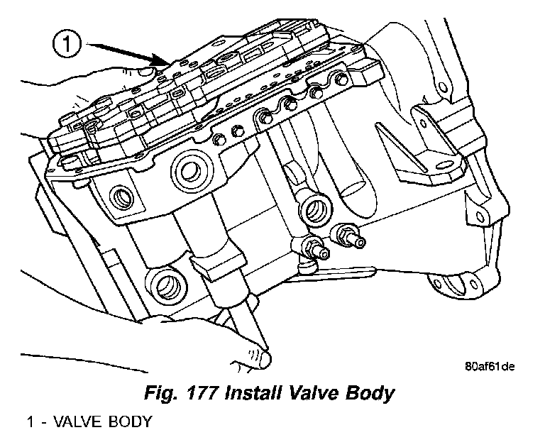
73. Install valve body (1) (Fig. 177) to transaxle. Rotate manual valve shaft fully clockwise to ease installation. Make sure park rod rollers are positioned within park guide bracket.
Fig. 178 Install Valve Body-to-Case Bolts:
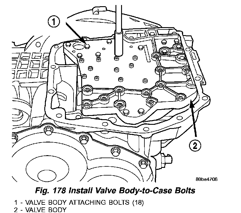
74. Install and torque valve body-to-case bolts (1) (Fig. 178) to 12 Nm (105 inch lbs.).
Fig. 179 Install Oil Filter:
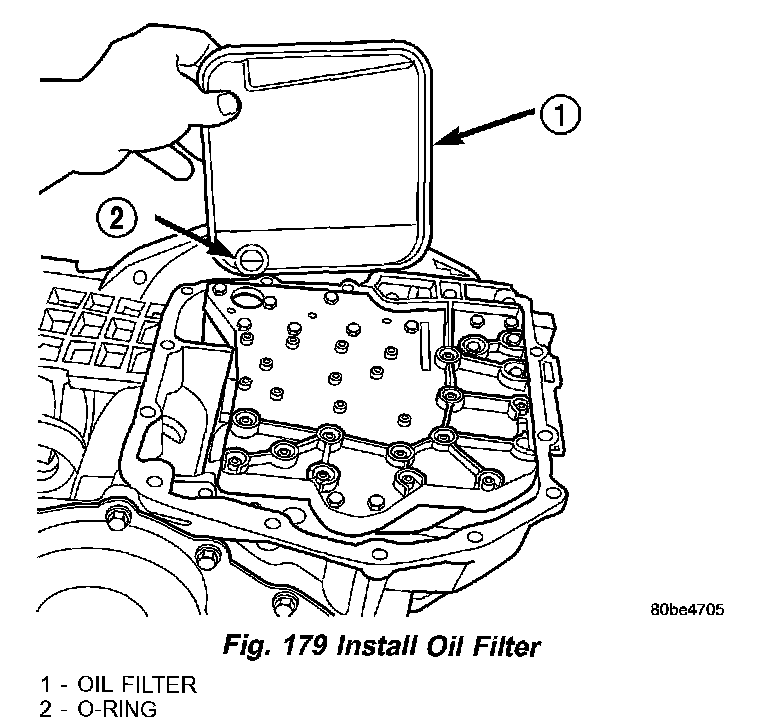
75. Install oil filter (1) (Fig. 179) and new O-ring (2).
Fig. 180 Install Oil Pan:
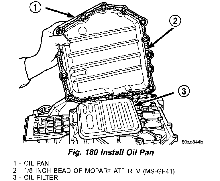
76. Apply an 1/8 bead of Mopar ATF RTV (MSGF41) (2) (Fig, 180) to oil pan (1) and immediately install to case.
77. Install oil pan-to-case bolts and torque to 19 Nm (165 inch lbs.).
Fig. 181 Solenoid/Pressure Switch Assembly and Gasket:
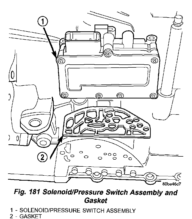
78. Install solenoid/pressure switch assembly (1) (Fig. 181) and gasket (2) to case.
Fig. 182 Solenoid Pack-to-Transaxle Bolts:
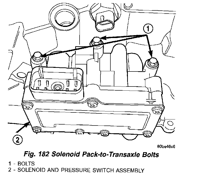
79. Install and tighten solenoid/pressure switch assembly-to-transaxle case bolts (1) to 12 Nm (110 inch lbs.) (Fig. 182).
80. Install and torque input and output speed sensors to case to 27 Nm (20 ft. lbs.).