Assembly
VALVE BODYASSEMBLY
NOTE: If valve body assembly is reconditioned, the PCM/TCM Quick Learn Procedure must be performed. .
Fig. 424 Springs and Valves Location:
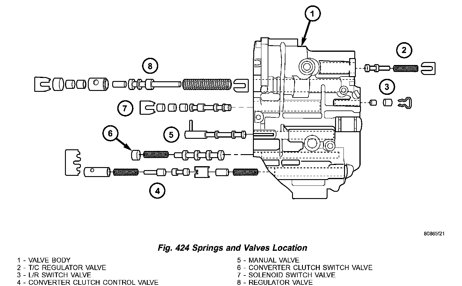
1. Install valves and springs (Fig. 424).
Fig. 425 Install Regulator Valve Spring Retainer using Tool 6302:
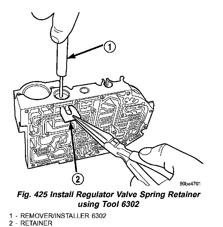
2. Install regulator valve spring retainer (2) (Fig. 425) using remover/installer 6302 (1).
Fig. 426 Install Dual Retainer Plate using Tool 6301:
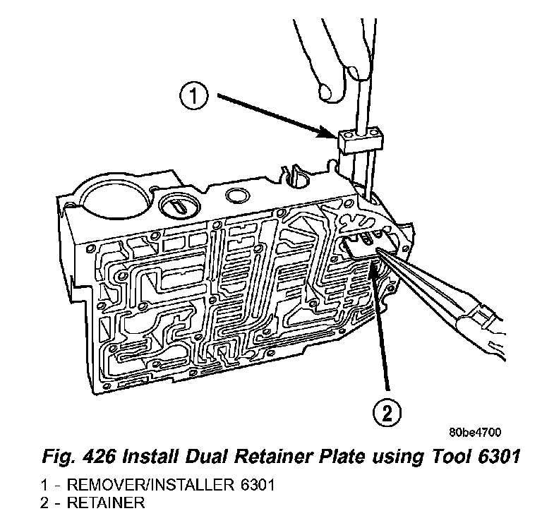
3. Install dual retainer plate (2) (Fig. 426) using remover/installer 6301 (1).
Fig. 427 Valve Retainer Location:
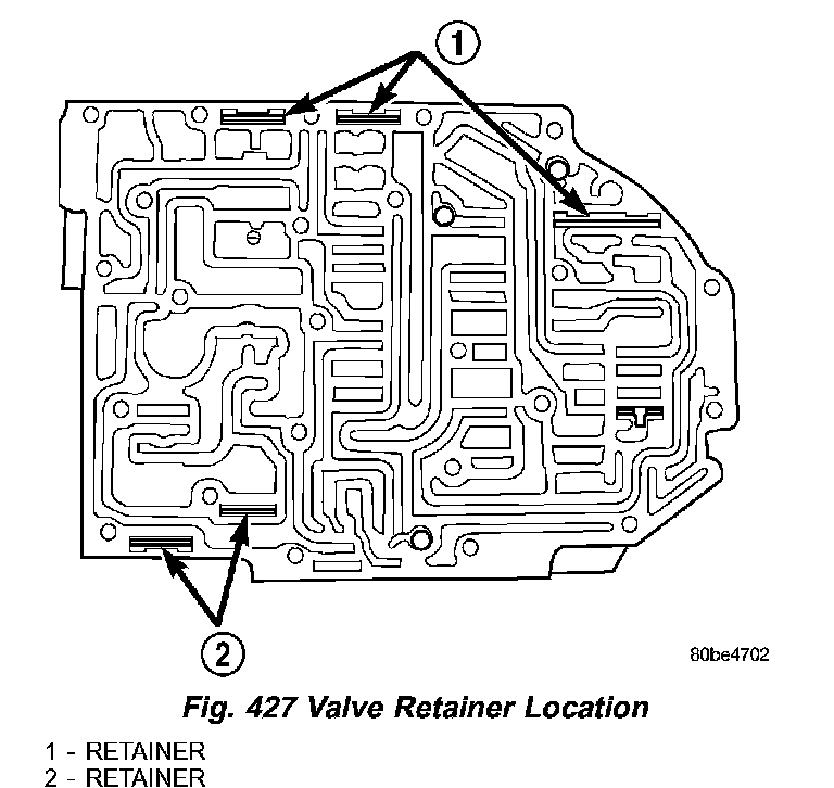
4. Verify that all retainers are installed (1,2) (Fig. 427). Retainers should be flush or below valve body surface.
Fig. 428 Ball Check Location:
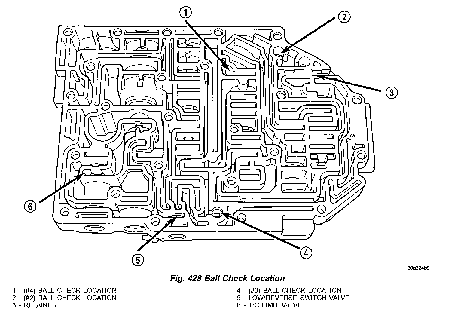
5. Install check balls into position (1,2 and 4) (Fig. 428). If necessary, secure them with petrolatum or transmission assembly gel for assembly ease.
Fig. 429 Install Thermal Valve:
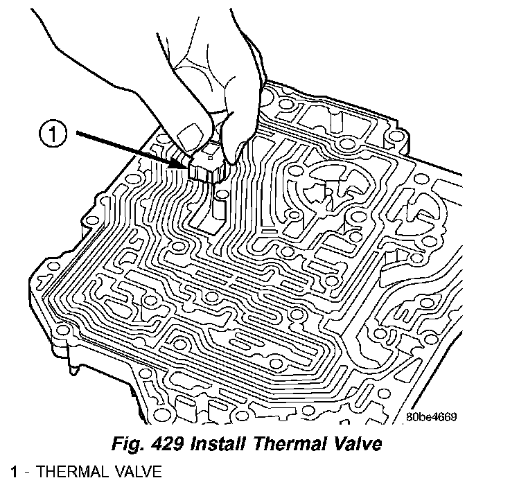
6. Install thermal valve (1) (Fig. 429) into transfer plate.
Fig. 430 Install Separator Plate:
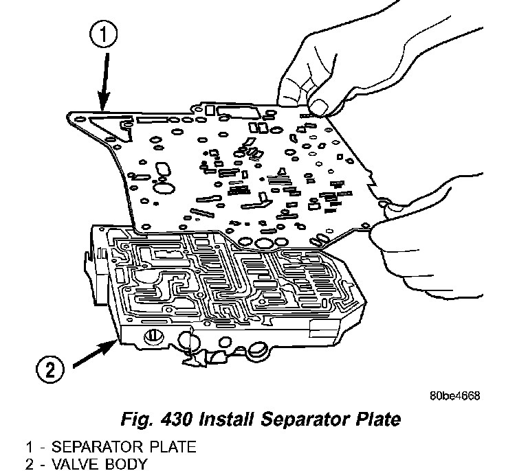
7. Install separator plate (1) (Fig. 430) to valve body (2).
Fig. 431 Install Overdrive Clutch (#5) Check Valve:
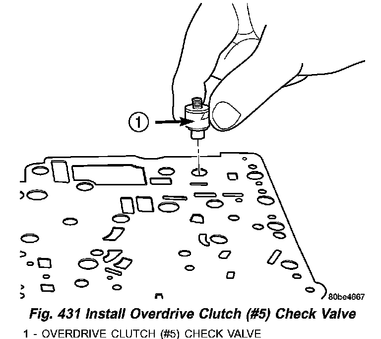
8. Install the overdrive clutch (#5) check valve (1) (Fig. 431) to separator plate.
Fig. 432 Install Oil Screen:
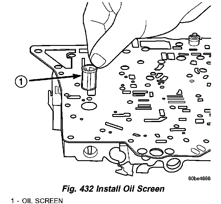
9. Install oil screen (1) (Fig. 432) to separator plate.
Fig. 433 Install Transfer Plate:
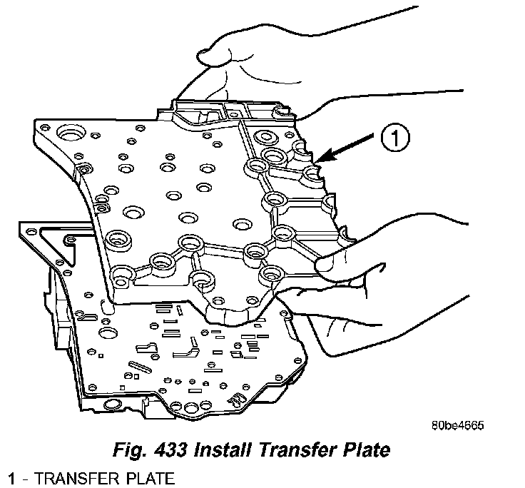
10. Install transfer plate (1) (Fig. 433) to valve body and separator plate. Make sure oil screen and #5 check valve do not bind.
Fig. 434 Install Valve Body to Transfer Plate Screws:
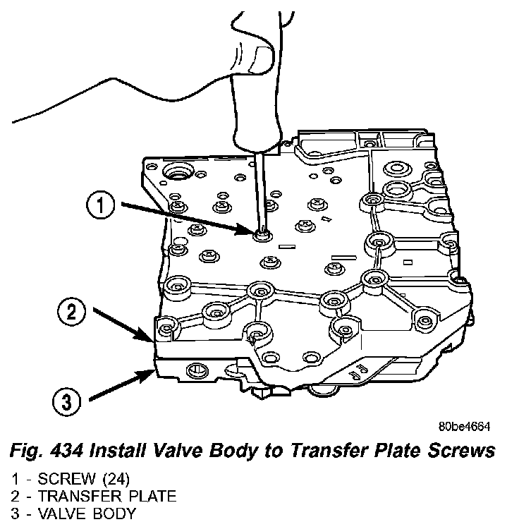
11. Install twenty-four transfer plate (Fig. 434) to valve body screws (1) and torque to 5 Nm (45 inch lbs.).
Fig. 435 2/4 Accumulator Assembly:
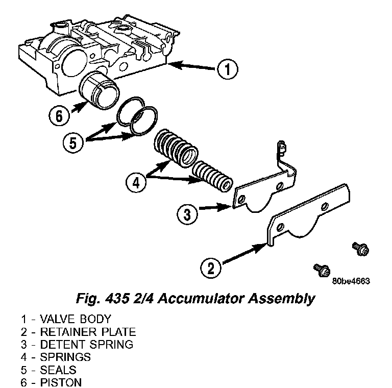
12. Install 2/4 Accumulator components (2,3,4,5 and 6) (Fig. 435).
Fig. 436 2/4 Accumulator Retaining Plate:
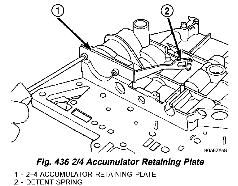
13. Torque 2/4 Accumulator retainer (1) (Fig. 436) to 5 Nm (45 inch lbs.).
Fig. 437 Install Manual Shaft/Rooster Comb and Transmission Range Sensor:
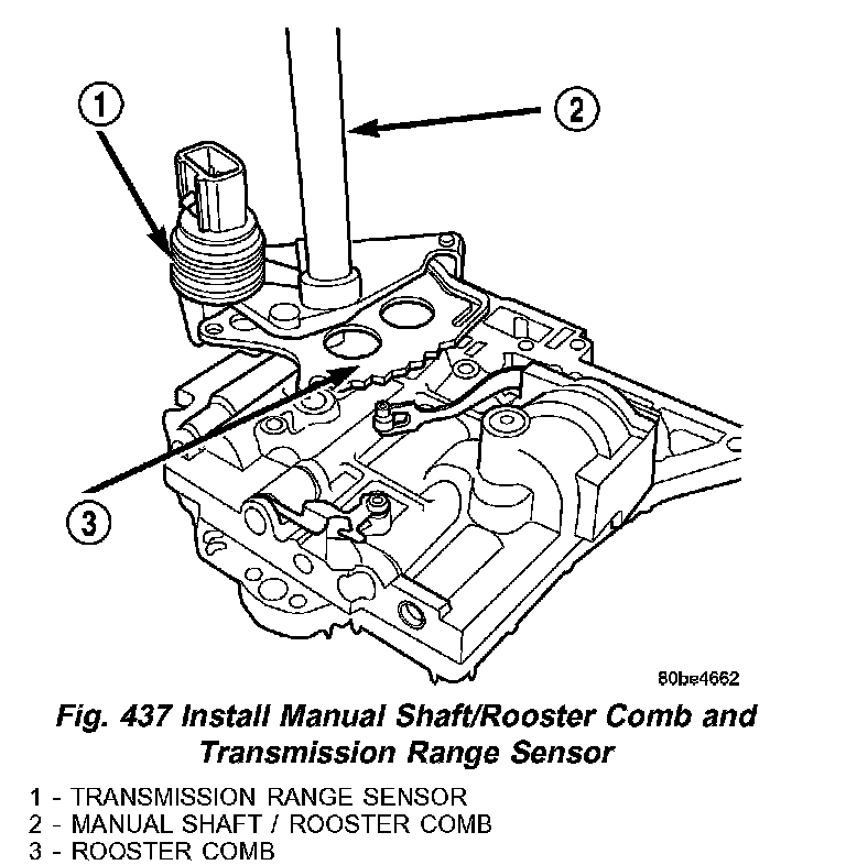
14. Install Manual Shaft/Rooster Comb (3) (Fig. 437) and Transmission Range Sensor (1).
Fig. 438 Install Transmission Range Sensor Retaining Screw:
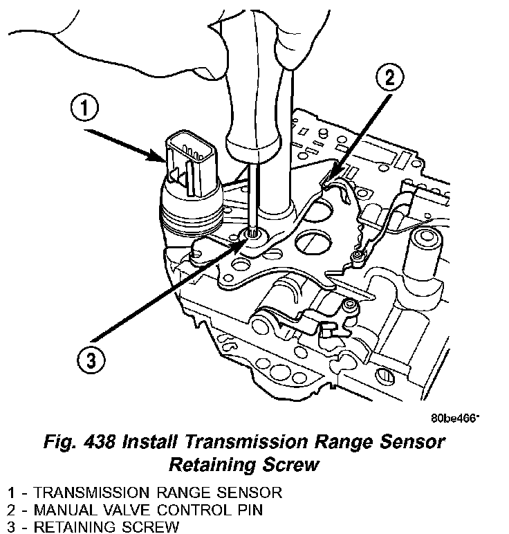
15. Make sure Manual Valve control pin (2) (Fig. 438) is contained within the rooster comb slot. Install Transmission Range Sensor retaining screw (3) and torque to 5 Nm (45 inch lbs.).
Fig. 439 Manual Shaft Seal:
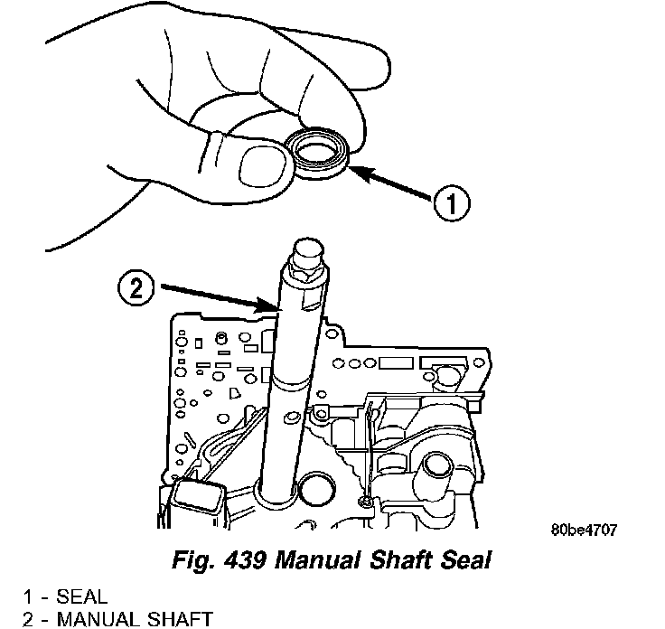
16. Install manual shaft seal (1) (Fig. 439).