Removal and Installation
DISTRIBUTOR (2.2L Engine)REMOVAL
Pick-Up Lead Connector And Splash Shield:
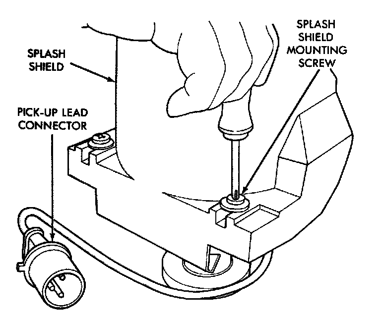
1. Disconnect distributor pick-up lead wire at wiring harness connector.
Pick-Up Lead Connector And Splash Shield:
2. Remove splash shield retaining screws.
Splash Shield:
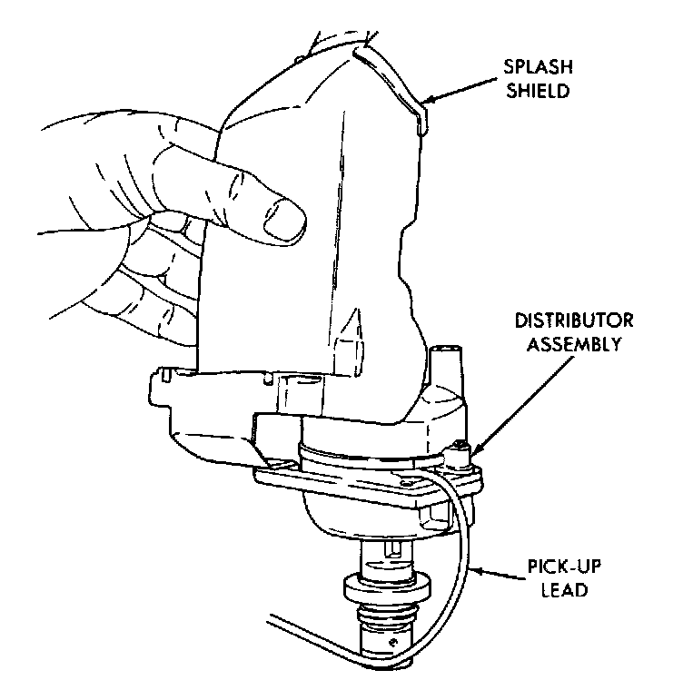
3. Remove splash shield.
Distributor Cap Retaining Screws:
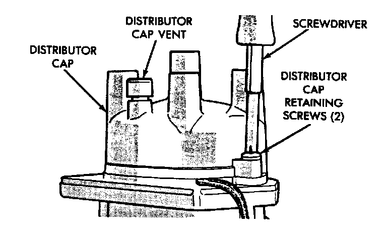
4. Loosen distributor cap retaining screws.
Distributor Cap:
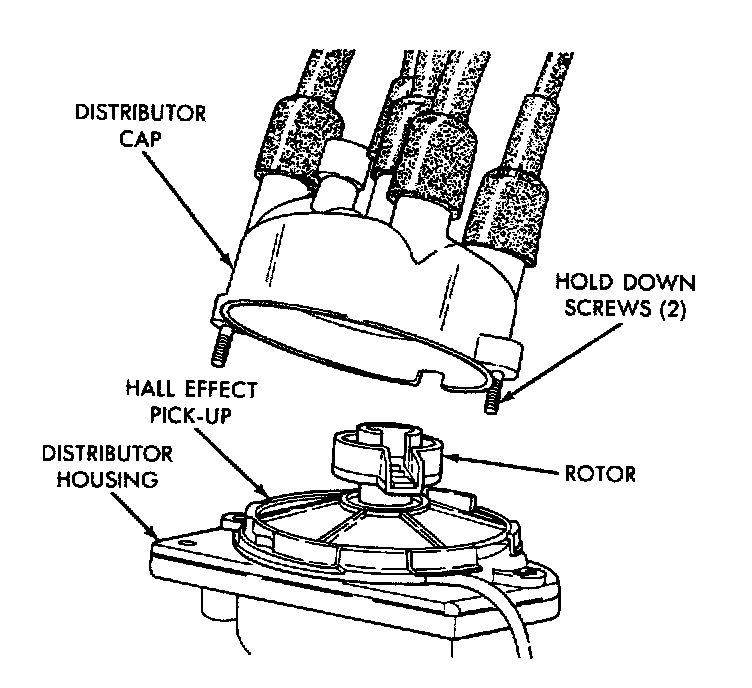
5. Lift off distributor cap.
6. Rotate engine crankshaft until the distributor rotor is pointing toward the cylinder block, scribe a mark on block at this point to indicate position of the rotor as reference when reinstalling distributor.
Distributor Hold Down 2.2L Engine:
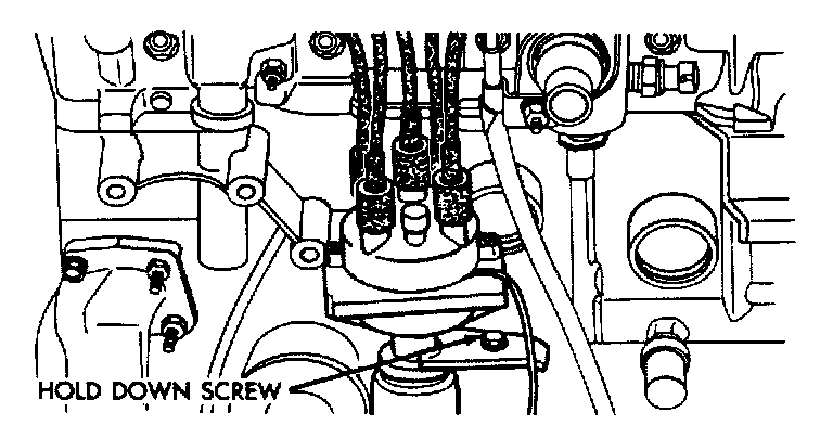
7. Remove distributor hold-down screw.
8. Carefully lift the distributor from the engine.
INSTALLATION
1. Position distributor in engine. Make certain that the 0-ring is properly seated on distributor. If 0-ring is cracked or nicked, replace with new one.
2. Carefully engage distributor drive with auxiliary shaft drive so that when distributor is installed properly, rotor will be in line with previously scribed line on cylinder block.
If engine has been cranked while distributor is removed, it will be necessary to establish proper relationship between the distributor shaft and No.1 piston position as follows:
a. Rotate the crankshaft until number one piston is at top of compression stroke. Pointer on clutch housing should be in line with the "0" TDC mark on flywheel.
b. Rotate rotor to a position just ahead of the number one distributor cap terminal.
c. Lower the distributor into the opening, engaging distributor drive with drive on auxiliary shaft. With distributor fully seated on engine, rotor should be under the cap number 1 tower.
Distributor Cap:
3. Install the distributor cap (make sure all high tension wires snap firmly in the cap towers).
Distributor Hold Down 2.2L Engine:
4. Install hold-down arm screw and tighten finger tight.
Splash Shield:
Pick-Up Lead Connector And Splash Shield:
5. Install splash shield.
6. Connect distributor hall effect pick-up lead wire at wiring harness connector.
7. Set ignition timing to specification (refer to Ignition Timing).