General System Description
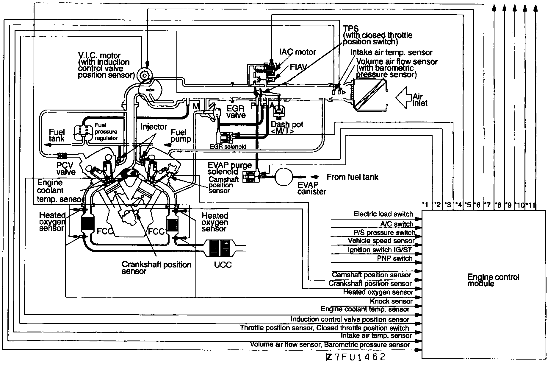
PURPOSE
The Electronically Controlled Multipoint Injection system (ECI-MULTI)maintains emission levels and fuel economy within government agency standards, while optimizing driveability. The system consists of an Engine Control Module (ECM), Control Relay, wiring, sensors and actuators.
OPERATION
The ECM uses an 8-bit microprocessor, Random Access Memory (RAM), Read Only Memory (ROM) and an Input/Output (I/0) interface. The control relay supplies positive current to the Purge Solenoid, ECM, and injectors.
The system also performs self-diagnostic procedures and provides back-up functions if certain circuits fail.
SENSORS/INPUTS
- A/C control units
- Air Flow Sensor (AFS)
- Barometric Pressure Sensor
- Battery voltage
- Crankshaft Position Sensor
- Detonation "Knock" Sensor
- EGR Temperature Sensor
- Electrical Load Switch
- Engine Coolant Temperature Sensor
- Engine Coolant Temperature Switch (A/C)
- Idle Position Switch
- Ignition Switch
- Ignition Timing Adjustment Connector
- Induction Control Valve Position Sensor
- Inhibitor Switch (A/T only)
- Intake Air Temperature Sensor
- 4 Oxygen Sensors
- Power Steering Load Switch
- Transaxle Control Unit (A/T only)
- Throttle Position Sensor
- Vehicle Speed Sensor
- Camshaft Position Sensor
ACTUATORS/OUTPUTS [1]
1 EVAP Purge Control Solenoid
2 Fuel Injector
3 EGR Solenoid
4 Idle Air Control Motor
5 Variable Induction Control Motor
6 A/C Relay
7 Fuel Pump Relay
8 Ignition Coil
9 Malfunction Indicator Light
10 Transaxle Control Unit (A/T only)
11 Heater Control
[1] The numbers correspond to the output lines from the ECM in the accompanying illustration.