Compressor Clutch / Coil Assembly Replacement
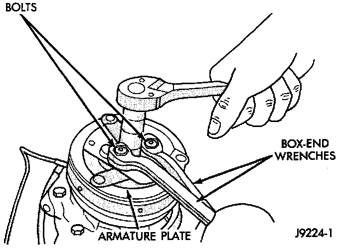
Fig 15 Compressor Shaft Nut Removal/Installation:
NOTE: The refrigerant system can remain fully-charged during compressor clutch, pulley, or coil replacement. The compressor clutch can be serviced in the vehicle.
REMOVAL
1. Remove the compressor. Do not remove the refrigerant lines or fittings.
2. Screw two 6 mm bolts into the threaded holes in the clutch armature plate. Hold the bolts with two wrenches to prevent the shaft from turning. Remove the compressor shaft nut.
3. Lightly tap the clutch plate with a plastic hammer and remove the plate and shim(s).
CAUTION: Do not use screwdrivers between the armature plate assembly and the rotor/pulley to remove the armature plate. This may damage the armature plate assembly.
4. Remove the pulley retaining snap ring with snap ring pliers. Remove the pulley assembly from the compressor. Use a plastic hammer, if required.
5. Loosen the clutch coil wire harness clamps and remove the wire harness from the compressor front coven Unplug the wire harness connectors from the thermal limiter switch.
WARNING: Take care that the snap ring does not fly out from the groove.
Fig 16 Clutch/Pulley/Coil Removal/Installation:
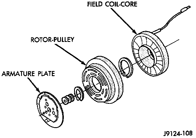
6. Remove the snap ring that secures the field coil assembly to the compressor front cover. Note the alignment of the field coil assembly when removing it.
INSPECTION
Examine the friction surfaces of the clutch rotor/ pulley and the armature plate for wear. The pulley and plate should be replaced if there is excessive wear or scoring.
If the friction surfaces are oily, inspect the shaft and nose area of the compressor for oil. If excessive oil is present, the shaft seal is leaking and the compressor must be replaced.
Check the clutch pulley hub bearing for roughness or excessive leakage of grease. Check for bearing grease contamination on the armature plate faces. Replace the bearing, if required.
CAUTION: The pulley and clutch plate were mated at the factory by a burnishing operation. No attempt should be made to separately replace either part. This will result in clutch slippage due to insufficient contact area.
INSTALLATION
1. Position the back of the clutch field coil on the compressor front cover. Be sure the locating pin on the back of the coil lines up with the indentation on the compressor front cover. This ensures the correct orientation of the coil and the wire harness.
2. Route the coil wire harness through the clamps on the compressor front cover and secure. Plug in the thermal limiter switch wire harness connectors.
3. Install the field coil retaining snap ring (bevel side outward) with snap ring pliers. Be certain that the snap ring is properly seated into the groove.
CAUTION: If the snap rings on the field coil or the pulley assembly are not fully seated, they will vibrate out. A clutch failure and damage to the compressor may result.
4. Position the pulley assembly onto the compressor.
CAUTION: Do not mar the pulley friction surface.
5. Install the pulley assembly retaining snap ring (bevel side outward) with snap ring pliers. Be certain that the snap ring is properly seated in the groove.
6. Place a trial stack of shims, 2.54 mm (0.10 in.) thick, on the compressor shaft.
Fig 17 Aligning Clutch Plate Splines:
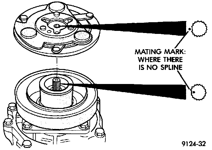
7. Install the clutch plate on the compressor shaft. Note the machined mating splines.
Fig 18 Check Clutch Air Gap:
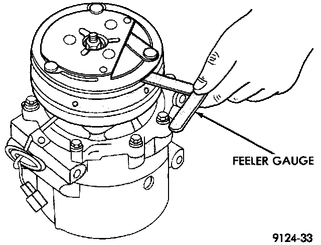
8. With the front clutch plate assembly tight against the shims, measure the air gap between the clutch plate and the pulley face with a feeler gauge. The air gap should be between 0.35 and 0.65 mm (0.013 and 0.025 inch). If the proper air gap is not obtained, add or subtract shims until the desired air gap is obtained.
9. Install the compressor shaft nut. Tighten the nut to 14.4 N.m (10.5 ft. lbs.).
10. The shims may compress after tightening the shaft nut. Check the air gap in four or more places to verify that the air gap is still correct. Spin the pulley for a final check.
11. Install the compressor.
CLUTCH BREAK-IN
After a new compressor clutch has been installed, cycle the compressor clutch approximately twenty times (five seconds on, then five seconds off). During this procedure, set the heater-A/C mode control switch in the Max (A/C) position, the blower motor switch in the highest speed position, and hold the engine speed at 1,500 - 2,000 rpm. This procedure (burnishing) will seat the opposing friction surfaces and provide a higher compressor clutch torque capability