Ignition Coil: Testing and Inspection
TESTING FOR SPARK AT COILCable Removal:
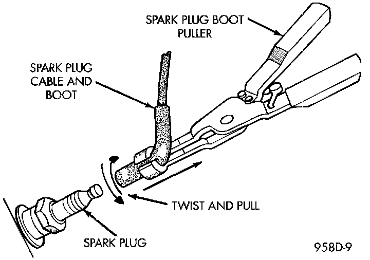
CAUTION: When disconnecting a high voltage cable from a spark plug or from the distributor cap, twist the rubber boot slightly (112 turn) to break it loose. Grasp the boot (not the cable) and pull it oft with a steady, even force.
Check For Spark - Typical:
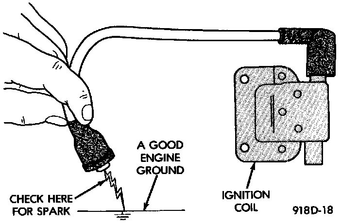
1. Disconnect the ignition coil secondary cable from center tower of the distributor cap. Hold the cable terminal approximately 12 mm (1/2 in.) from a good engine ground.
WARNING: BE VERY CAREFUL WHEN THE ENGINE IS CRANKING. DO NOT PUT YOUR HANDS NEAR THE PULLEYS, BELTS OR THE FAN. DO NOT WEAR LOOSE FITTING CLOTHING.
2. Rotate (crank) the engine with the starter motor and observe the cable terminal for a steady arc. If steady arcing does not occur, inspect the secondary coil cable. Refer to Spark Plug Cables. Also inspect the distributor cap and rotor for cracks or burn marks. Repair as necessary. If steady arcing occurs, connect ignition coil cable to the distributor cap.
3. Remove a cable from one spark plug.
4. Using insulated pliers, hold the cable terminal approximately 12 mm (1/2 in.) from the engine cylinder head or block while rotating the engine with the starter motor. Observe the spark plug cable terminal for an arc. If steady arcing occurs, it can be expected that the ignition secondary system is operating correctly. (If the ignition coil cable is removed for this test, instead of a spark plug cable, the spark intensity will be much higher). If steady arcing occurs at the spark plug cables, but the engine will not start, connect the DRB scan tool. Refer to the appropriate Powertrain Diagnostic Procedures.
IGNITION COIL TEST
Ignition Coil - Typical:
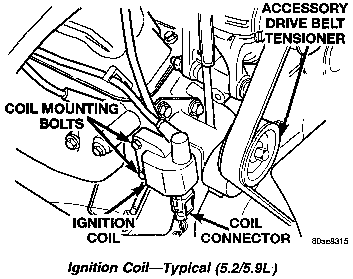
To perform a complete test of the ignition coil and its circuitry, refer to the DRB scan tool. Also refer to the appropriate Powertrain Diagnostics Procedures. To test the coil only, refer to the following:
The ignition coil is designed to operate without an external ballast resistor.
Inspect the ignition coil for arcing. Test the coil according to coil tester manufacturer's instructions. Test the coil primary and secondary resistance.
Replace any coil that does not meet specifications. Refer to the IGNITION COIL RESISTANCE chart.
Ignition Coil Resistance
Coil Manufacturer = Diamond
Primary Resistance 21-27° C (70-80° F) = 0.97 - 1.18 Ohms
Secondary Resistance 21-27° C (70-80° F) = 11,300 - 15,300 Ohms
Coil Manufacturer = Toyodenso
Primary Resistance 21-27° C (70-80° F) = 0.95 - 1.20 Ohms
Secondary Resistance 21-27° C (70-80° F) = 11,300 - 13,300 Ohms
If the ignition coil is being replaced, the secondary spark plug cable must also be checked. Replace cable if it has been burned or damaged.
Arcing at the tower will carbonize the cable boot, which if it is connected to a new ignition coil, will cause the coil to fail.
If the secondary coil cable shows any signs of damage, it should be replaced with a new cable and new terminal. Carbon tracking on the old cable can cause arcing and the failure of a new ignition coil.
Failure To Start Test
To prevent unnecessary diagnostic time and wrong test results, the Testing For Spark At Coil test should be performed prior to this test.
WARNING: SET PARKING BRAKE OR BLOCK THE DRIVE WHEELS BEFORE PROCEEDING WITH THIS TEST.
1. Unplug the ignition coil harness connector at the coil.
2. Connect a set of small jumper wires (18 gauge or smaller) between the disconnected harness terminals and the ignition coil terminals.
3. Attach one lead of a voltmeter to the positive (12 volt) jumper wire. Attach the negative side of voltmeter to a good ground. Determine that sufficient battery voltage (12.4 volts) is present for the starting and ignition systems.
4. Determine that sufficient battery voltage (12.4 volts) is present for the starting and ignition systems.
5. Crank the engine for 5 seconds while monitoring the voltage at the coil positive terminal:
6.
- If the voltage remains near zero during the entire period of cranking, refer to On-Board Diagnostics. Check the Powertrain Control Module (PCM) and auto shutdown relay.
- If voltage is at or near battery voltage and drops to zero after 1-2 seconds of cranking, check the powertrain control module circuit. Refer to On-Board Diagnostics.
PCM And Three 32-Way Connectors:
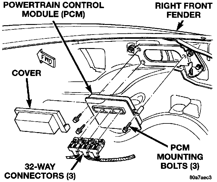
- If voltage remains at or near battery voltage during the entire 5 seconds, turn the key off. Remove the three 32-way connectors from the PCM. Check 32-way connectors for any spread terminals or corrosion.
7. Remove test lead from the coil positive terminal. Connect an 18 gauge jumper wire between the battery positive terminal and the coil positive terminal.
Special Jumper Ground-to-Coil Negative Terminal:
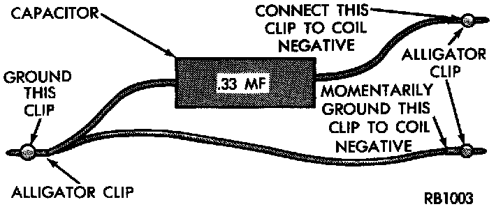
8. Make the special jumper shown. Using the jumper, momentarily ground the ignition coil driver circuit at the PCM connector (cavity A-7). A spark should be generated at the coil cable when the ground is removed.
9. If spark is generated, replace the PCM.
10. If spark is not seen, use the special jumper to ground the coil negative terminal directly.
11. If spark is produced, repair wiring harness for an open condition.
12. If spark is not produced, replace the ignition coil.