Alignment: Service and Repair
WHEEL ALIGNMENTHEIGHT MEASUREMENT
The vehicle suspension height MUST be measured and adjusted before performing wheel alignment procedure. Also when front suspension components have been replaced. This measure must be performed with the vehicle supporting it's own weight and taken on both sides of the vehicle.
FRONT RIDE HEIGHT MEASUREMENT
1. Inspect tires and set to correct pressure.
2. Jounce the front of the vehicle.
3. With vehicle on level ground or hoist, make the following measurements:
a. Front wheel spindle (center) to ground vertical distance.
b. Measure the center of front face of bolt on the rear leg of lower control arm and the center of front face of front leg of control arm to ground vertical distance and take the average height.
c. Difference between spindle and control arm bolt to ground average distance should be 71 mm ± 6 mm. Note that the control arm bolt is lower than the spindle.
4. After making any ride height adjustment, roll vehicle preferably jouncing it also, to relieve camber Effects and then re-measure Lower control arm bolt to ground height.
5. Repeat the previous steps until the ride height is within specifications.
REAR RIDE HEIGHT MEASUREMENT
1. Inspect tires and set to correct pressure.
2. Jounce the front of the vehicle.
3. With vehicle on level ground or hoist, make the following measurements:
a. Distance from the landing pad of the jounce bumper on the axle side to the jounce bumper cup lip of the frame side.
b. The difference between the jounce bumper landing pad and the jounce bumper cup lip the reading should be 148 mm ±10 mm for 9.25 axle, 154 mm ±10 mm for 8.25 axle.
TOE ADJUSTMENT
SUSPENSION HEIGHT MEASUREMENT MUST BE PERFORMED BEFORE AN ALIGNMENT.
The wheel toe position adjustment is the final adjustment.
1. Start the engine and turn wheels both ways before straightening the wheels. Secure the steering wheel with the front wheels in the straight-ahead position.
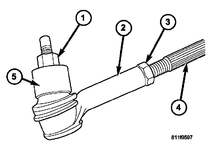
2. Loosen the tie rod jam nuts (3).
NOTE: Each front wheel should be adjusted for one-half of the total toe position specification. This will ensure the steering wheel will be centered when the wheels are positioned straight-ahead.
3. Adjust the wheel toe position by turning the inner tie rod (4) as necessary
4. Tighten the tie rod jam nut (3) to 75 Nm (55 ft. lbs.).
5. Verify the specifications.
6. Turn off engine.
CAMBER, CASTER AND TOE ADJUSTMENT
Camber and caster angle adjustments involve changing the position of the lower control arm with the slots in the frame brackets to move the lower control arm inwards or outwards for proper adjustment. This can be achieved by using a socket on the head of the cam bolt and turning clockwise or counterclockwise to achieve the proper specification.
NOTE: Both front and rear lower control arm cam bolts are adjustable.
NOTE: Camber and caster adjustments must be made at the lower control arm The upper control arm is not adjustable.
NOTE: When the lower control arm cam bolts are loosened the lower control arm will normally go outwards automatically with the weight of the vehicle.
CASTER
Moving the rear position of the lower control arm at the frame in or out, will change the caster angle significantly and camber angle only slightly To maintain the camber angle while adjusting caster, move the rear of the lower control arm in or out. Then move the front of the lower control arm slightly in the opposite direction.
CAMBER
Move both the front and rear of the lower control arm together in or out. This will change the camber angle significantly and caster angle slightly. After adjustment is made tighten the lower control arm bolt & nuts to 203 Nm (150 ft. lbs.).
TOE ADJUSTMENT
The wheel toe position adjustment is the final adjustment.
1. Start the engine and turn wheels both ways before straightening the wheels. Secure the steering wheel with the front wheels in the straight-ahead position.
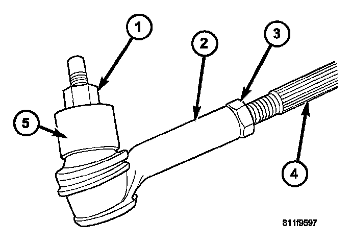
2. Loosen the tie rod jam nuts (3).
NOTE: Each front wheel should be adjusted for one-half of the total toe position specification. This will ensure the steering wheel will be centered when the wheels are positioned straight-ahead.
3. Adjust the wheel toe position by turning the inner tie rod (4) as necessary.
4. Tighten the tie rod jam nut (3) to 75 Nm (55 ft. lbs.).
5. Verify the specifications.
6. Turn off engine.