Input Clutch Assembly
INPUT CLUTCH ASSEMBLYDISASSEMBLY
Fig. 213 Input Clutch Hub, Retainer, and OD/Reverse Piston:
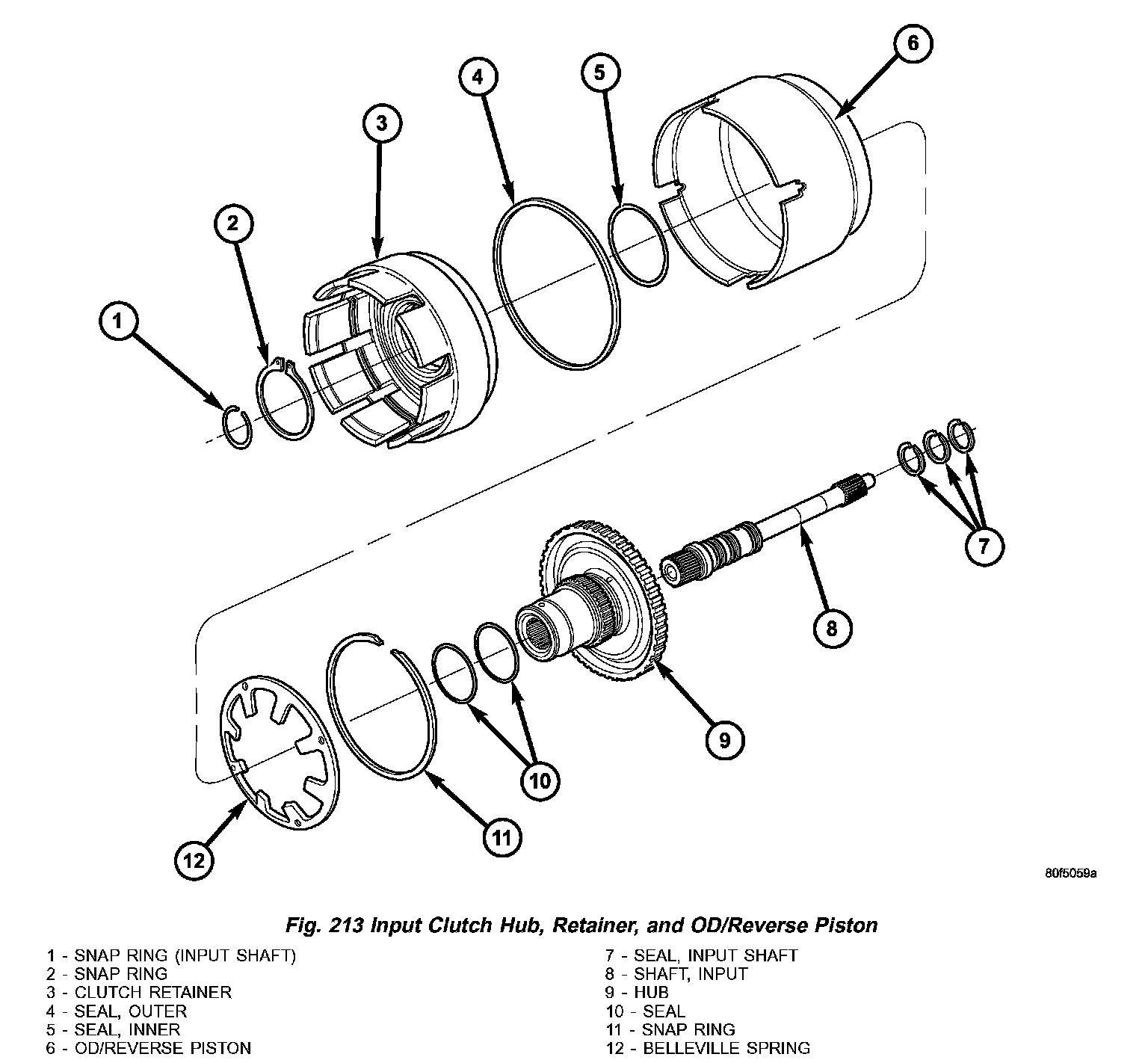
Refer to the exploded view (Fig. 213) as necessary when performing the following steps.
1) Mount input clutch assembly to Input Clutch Pressure Fixture 8391.
Fig. 214 Tapping Reaction Plate:
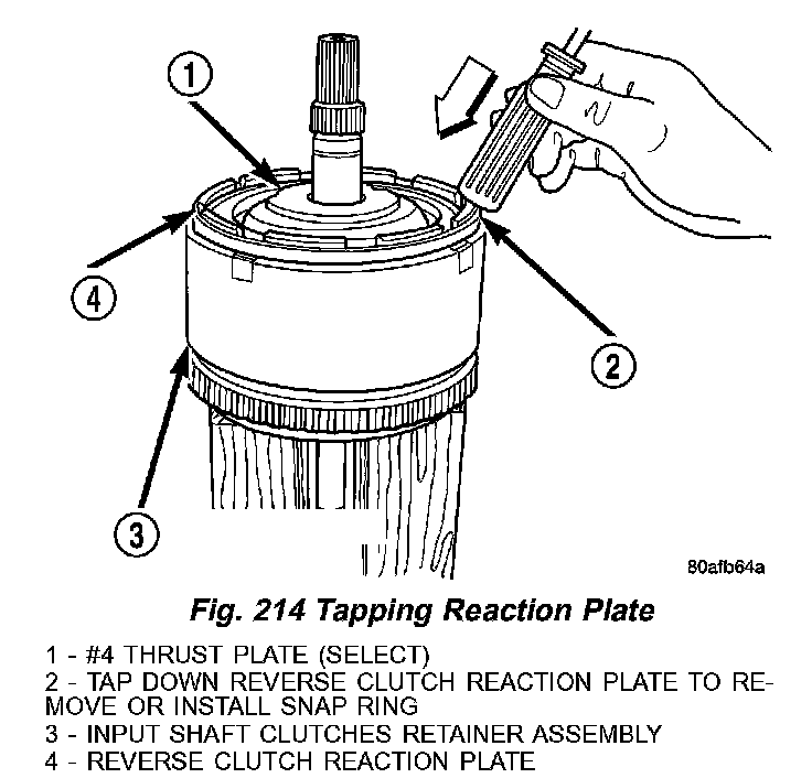
2) Tap down reverse clutch reaction plate to release pressure from snap ring (2) (Fig. 214).
Fig. 215 Reverse Clutch Snap Ring:
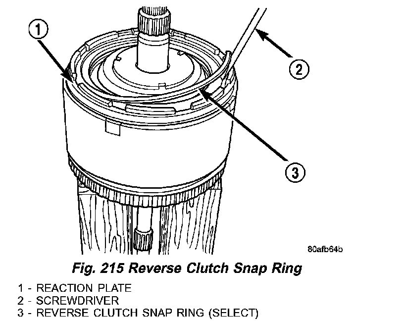
3) Remove reverse clutch snap ring (3) (Fig. 215).
Fig. 216 Pry Reverse Clutch Reaction Plate:
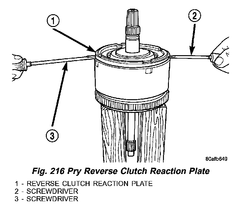
4) Pry up (2,3) (Fig. 216) and remove reverse clutch reaction plate (1).
Fig. 217 Reverse Clutch Assembly:
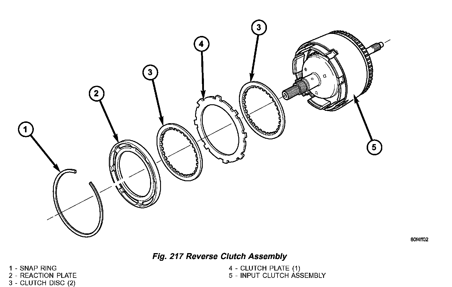
5) Remove reverse clutch pack (1,2,3 and 4) (Fig. 217). Tag components for assembly identification.
Fig. 218 Overdrive Clutch Assembly:
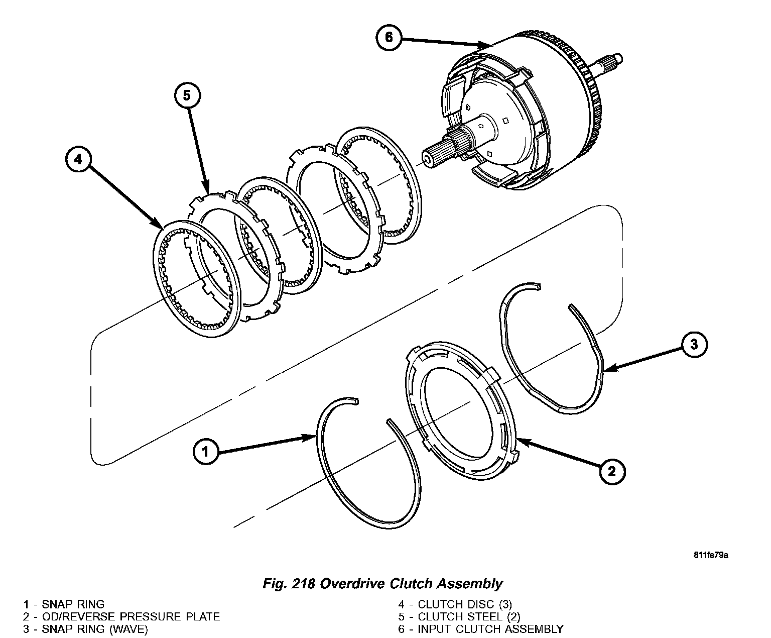
6) Remove the OD/Reverse pressure plate snap ring (1) (Fig. 218).
7) Remove OD/Reverse pressure plate (2).
8) Remove OD/Reverse pressure plate wave snap ring (3).
9) Remove OD clutch pack (4,5). Tag components for assembly identification.
Fig. 219 Overdrive/Underdrive Shafts:
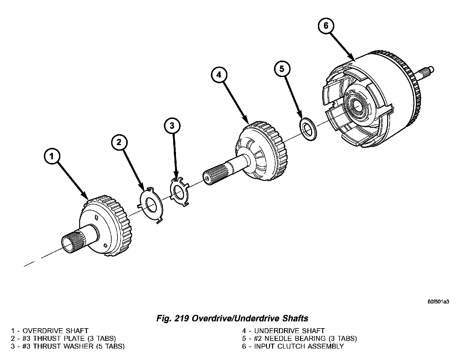
10) Remove and inspect OD (1) (Fig. 219) and UD (4) Shafts, as well as #3 thrust washer (3) and plate (2), and #2 needle bearing (5).
Fig. 220 Underdrive Clutch Assembly:
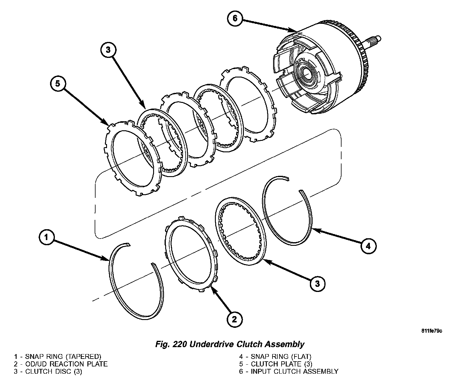
11) Remove the OD/UD reaction plate (2) (Fig. 220) tapered snap ring (1), reaction plate, and first friction disc (3).
Fig. 221 UD Spring Retainer Snap Ring:
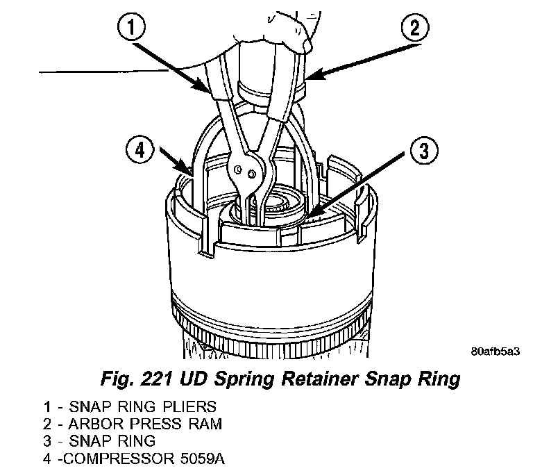
12) Remove the UD clutch flat snap ring (3) (Fig. 221) and rest of UD clutch pack. Tag clutch pack for assembly identification.
CAUTION: Compress return spring just enough to remove or install snap ring.
13) Using Compressor 5059A (4) and an arbor press (2), compress UD clutch piston/spring enough to remove snap ring (3).
Fig. 222 Underdrive Clutch Piston, Spring and Retainer:
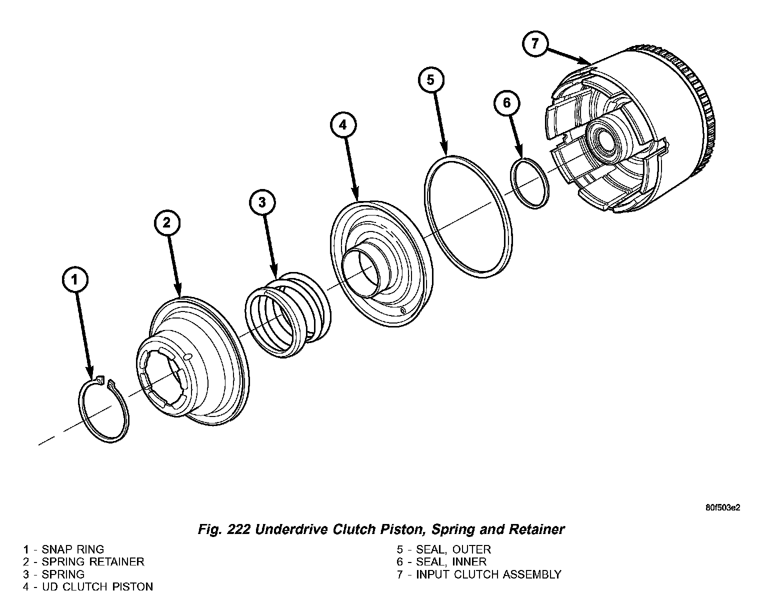
14) Remove spring retainer (2) (Fig. 222), spring (3), and piston (4).
Fig. 223 Input Hub Tapered Snap Ring:
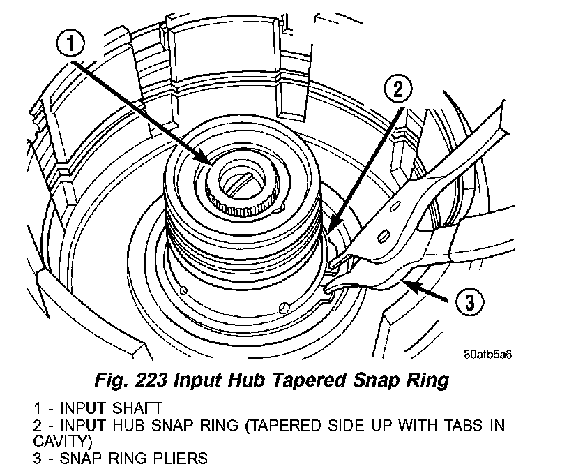
15) Remove input hub tapered snap ring (2) (Fig. 223).
Fig. 224 Tap on Input Hub:
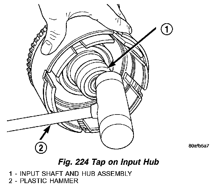
16) Tap on input hub (1) (Fig. 224) with soft faced hammer (2) and separate input hub from OD/Reverse piston and clutch retainer.
Fig. 225 Pull Retainer from Piston:
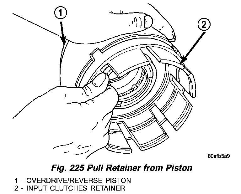
17) Separate clutch retainer (2) (Fig. 225) from OD/Reverse piston (1).
Fig. 226 Install Snap Ring:
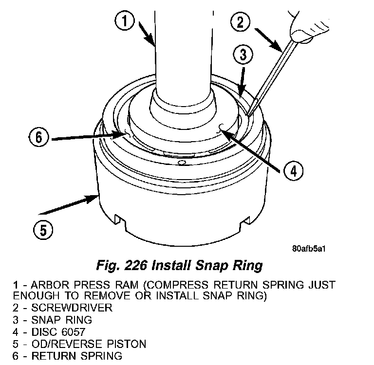
18) Using Disc 6057 (4) (Fig. 226) and an arbor press, compress return OD/Reverse piston return spring just enough to remove snap ring (3).
Fig. 227 Remove Input Shaft Snap Ring:
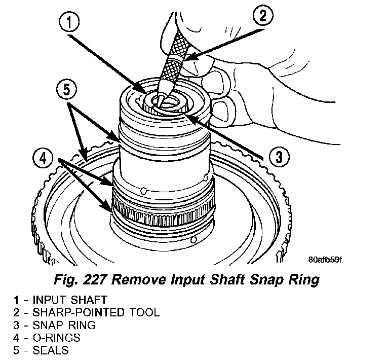
19) Remove input shaft to input clutch hub snap ring (3) (Fig. 227).
Fig. 228 Remove Input Shaft:
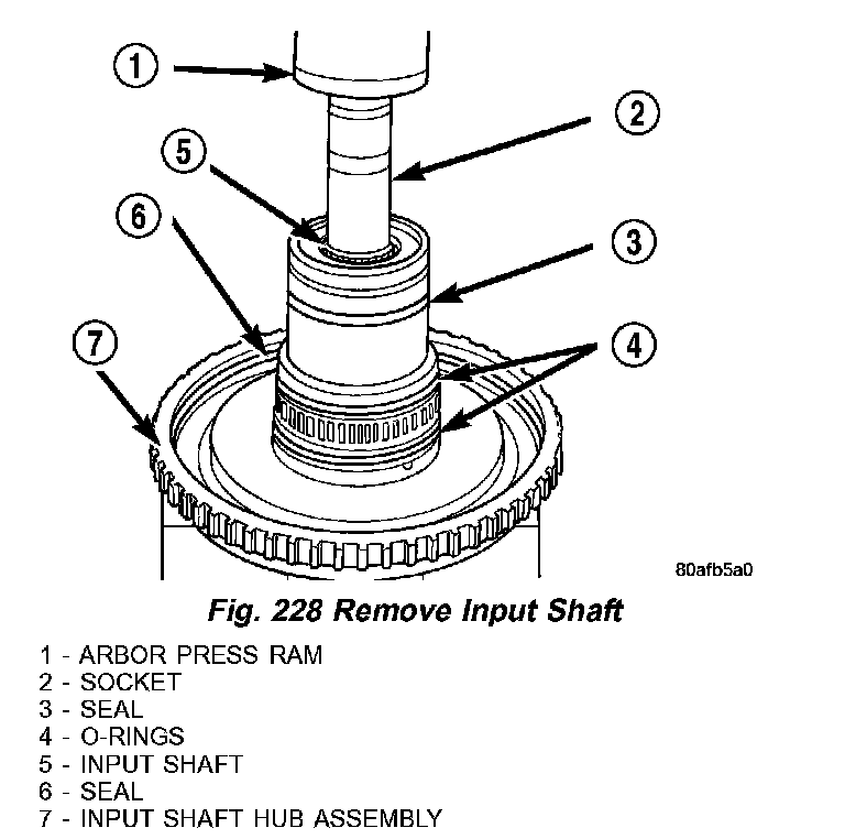
20) Using a suitably sized socket (2) (Fig. 228) and an arbor press (1), remove input shaft from input shaft hub (7).
ASSEMBLY
Use petrolatum on all seals to ease assembly of components.
Fig. 229 Install Input Shaft:
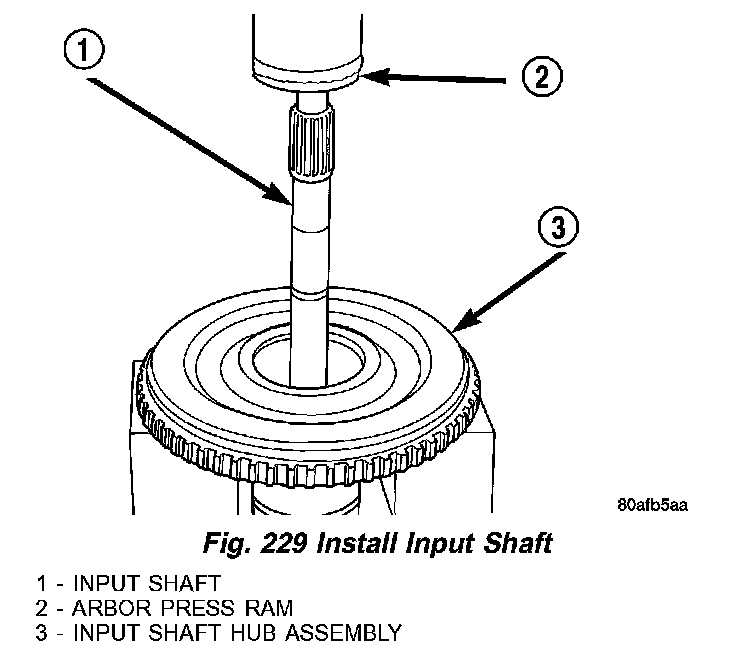
1) Using an arbor press (2) (Fig. 229), install input shaft (1) to input shaft hub (3).
Fig. 230 Install Input Shaft Snap Ring:
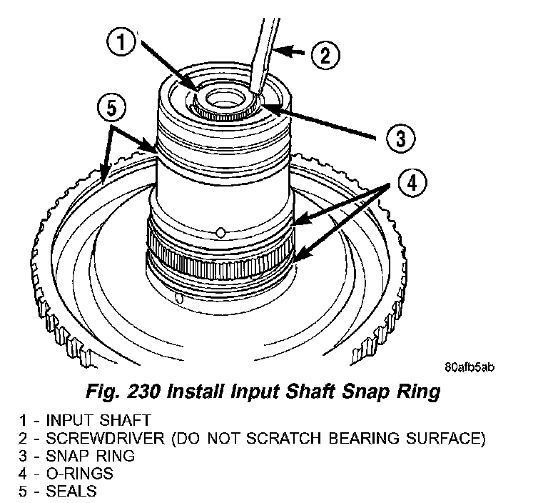
2) Install input shaft snap ring (3) (Fig. 230).
Fig. 231 Return Spring and Snap Ring:
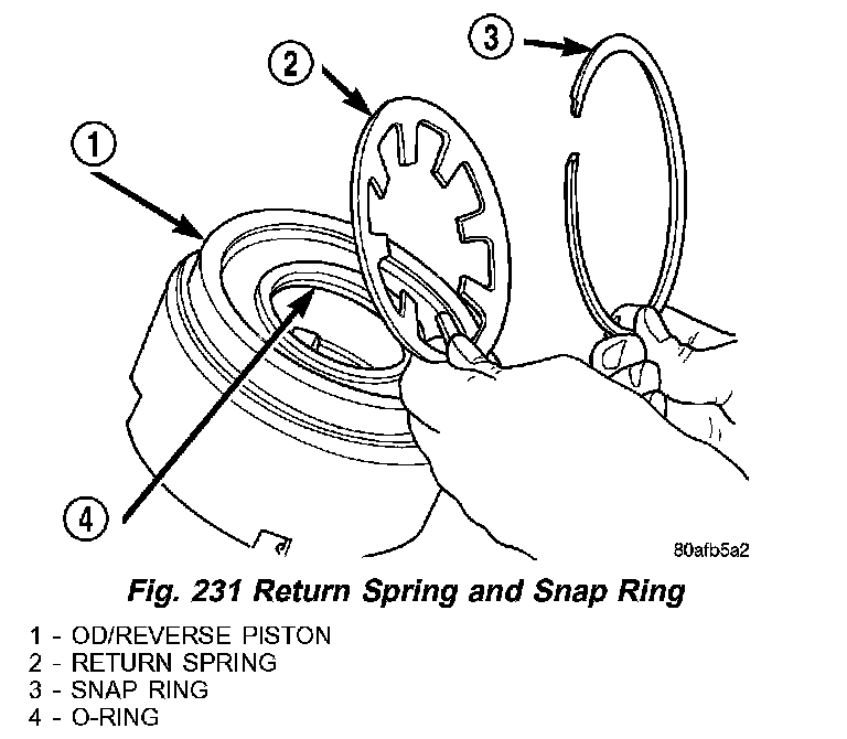
3) Place OD/Reverse piston (1) (Fig. 231) return spring (2) and snap ring (3) into position.
Fig. 232 Install Snap Ring:
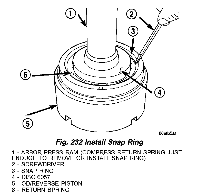
4) Using an arbor press (1) (Fig. 232) and Disc 6057 (4), Install OD/Reverse piston (5) return spring (6) and snap ring (3).
Fig. 233 Install OD/Reverse Piston:
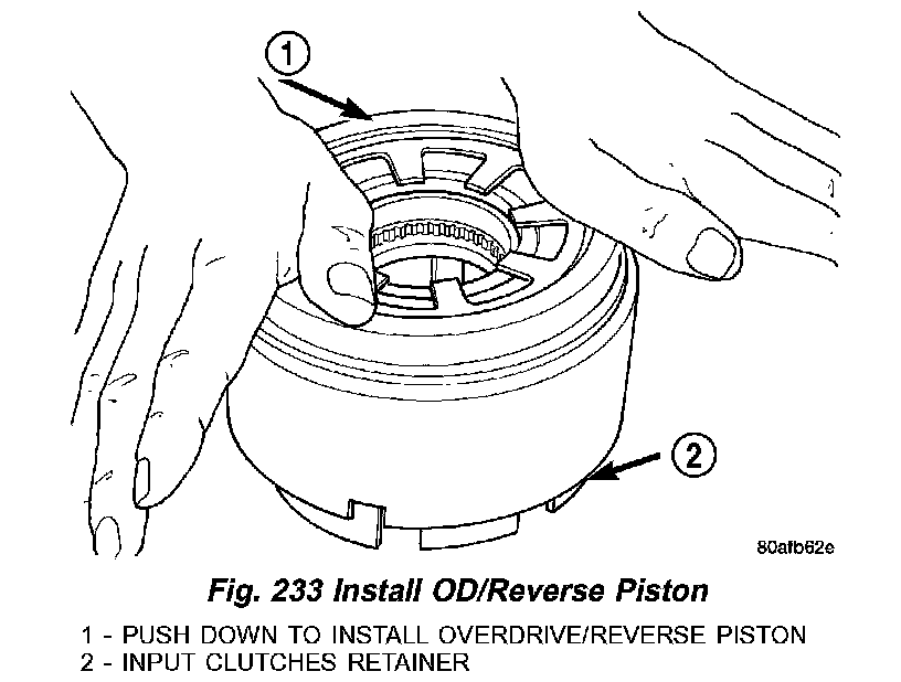
5) Install the OD/Reverse piston assembly (1) (Fig. 233) to the input clutch retainer (2).
Fig. 234 Install Input Shaft Hub Assembly:
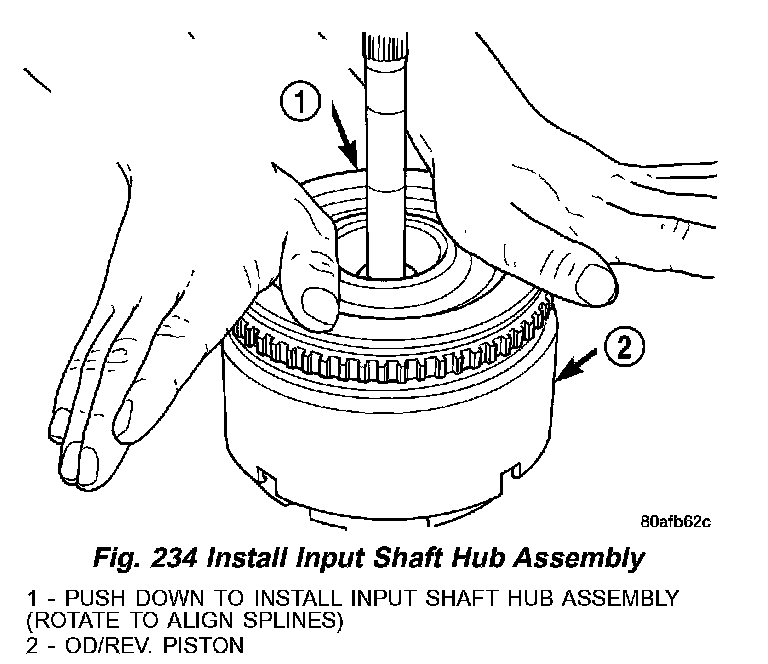
6) Install the input hub/shaft assy. (1) (Fig. 234) to the OD/Reverse piston/clutch retainer assembly (2).
Fig. 235 Install Input Hub Tapered Snap Ring:
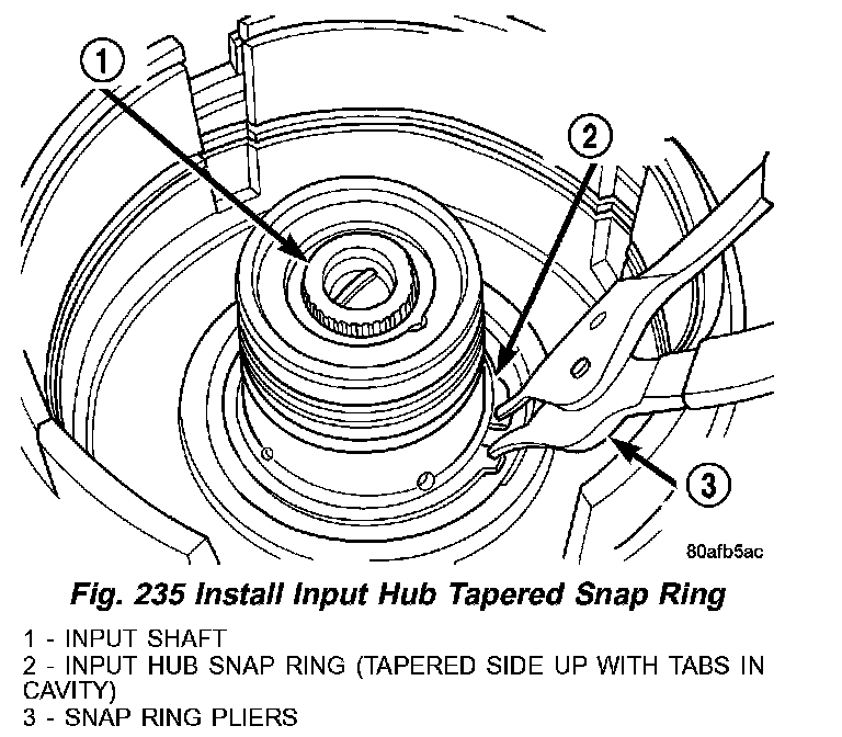
7) Install input hub tapered snap ring (2) (Fig. 235).
Fig. 236 Underdrive Clutch Piston:
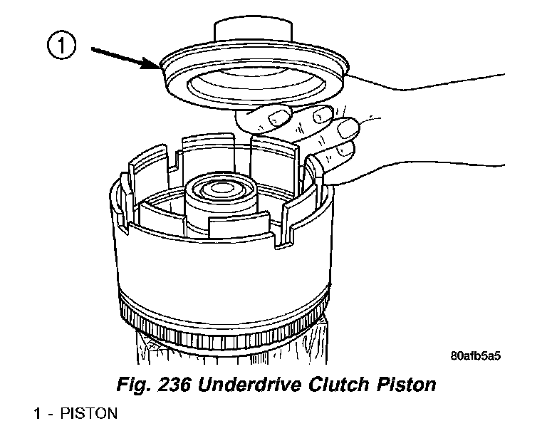
8) Install UD clutch piston (1) (Fig. 236).
Fig. 237 Seal Compressor Installer 5067:
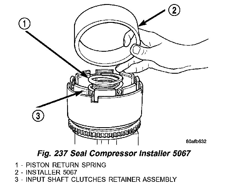
Fig. 238 Underdrive Clutch Piston, Spring and Retainer:
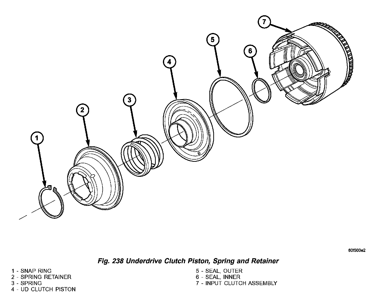
9) Install UD piston return spring (1) (Fig. 237) and Installer 5067 (2). Refer to the exploded view as necessary when performing the following steps. (Fig. 238)
Fig. 239 UD Return Spring and Retainer:
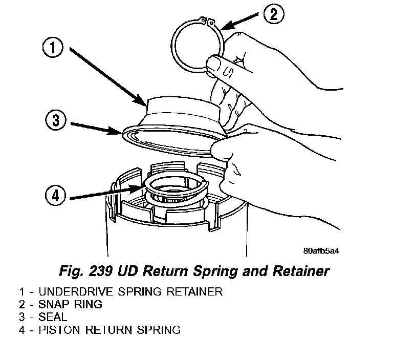
10) Place the UD spring retainer (1) (Fig. 239) and snap ring (2) into position.
Fig. 240 Install UD Spring Retainer and Snap Ring:
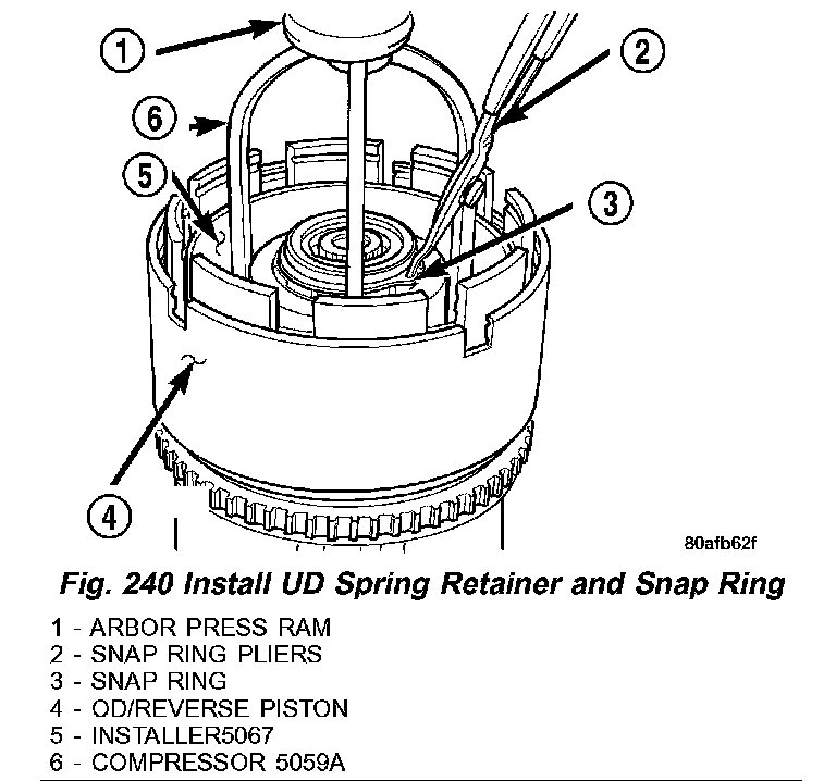
11) Using Compressor 5059A (6) (Fig. 240) and an arbor press (1), Install the UD spring retainer and snap ring (3) Compress just enough to install snap ring (3).
CAUTION: Compress return spring just enough to install snap ring.
Fig. 241 Install Underdrive Clutch Pack:
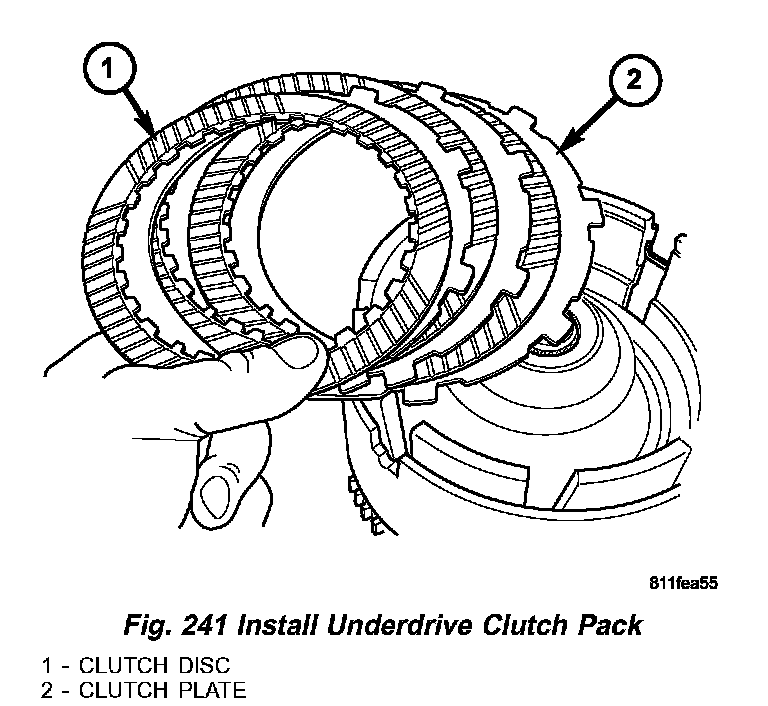
12) Install the UD clutch pack (1,2) (Fig. 241). Leave out upper disc, until snap ring is installed.
Fig. 242 UD Clutch Flat Snap Ring:
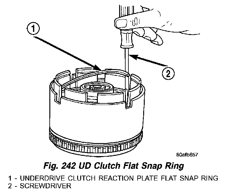
13) Install the UD clutch flat snap ring (1) (Fig. 242) using a screwdriver (2).
Fig. 243 Install Last UD Clutch Disc:
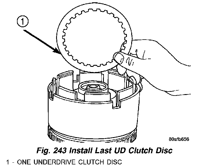
14) Install the last UD clutch disc (1) (Fig. 243).
Fig. 244 OD/UD Reaction Plate:
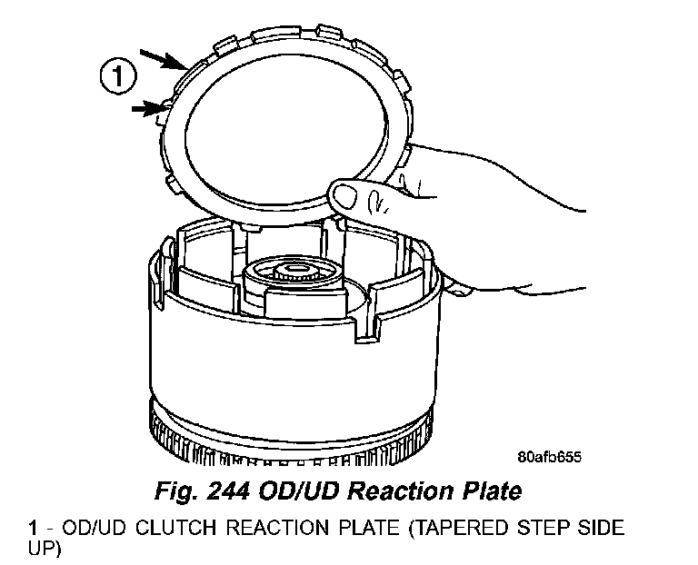
15) Place the OD/UD clutch reaction plate (1) (Fig. 244) and snap ring into position. The OD/UD clutches reaction plate has a step on both sides. Install the OD/UD clutches reaction plate tapered step side up.
Fig. 245 Tapered Snap Ring:
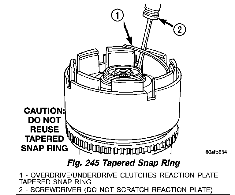
16) Install the snap ring (1) (Fig. 245) using a screwdriver (2).
NOTE: Snap ring ends must be located within one finger of the input clutch hub. Be sure that snap ring is fully seated, by pushing with screwdriver, into snap ring groove all the way around.
Fig. 246 Seating Tapered Snap Ring:
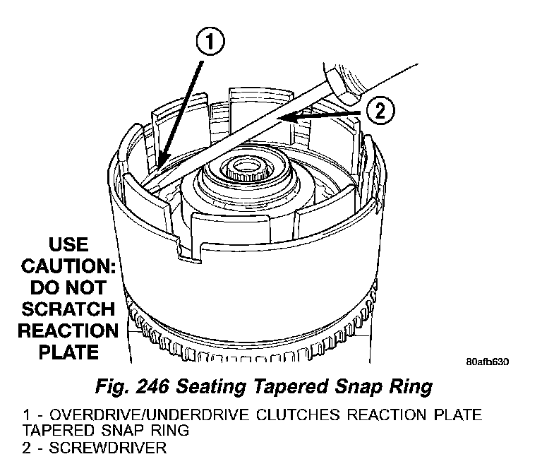
17) Seat tapered snap ring (1) (Fig. 246) to ensure proper installation.
Fig. 247 Input Clutch Assembly on Pressure FixtureTool 8391:
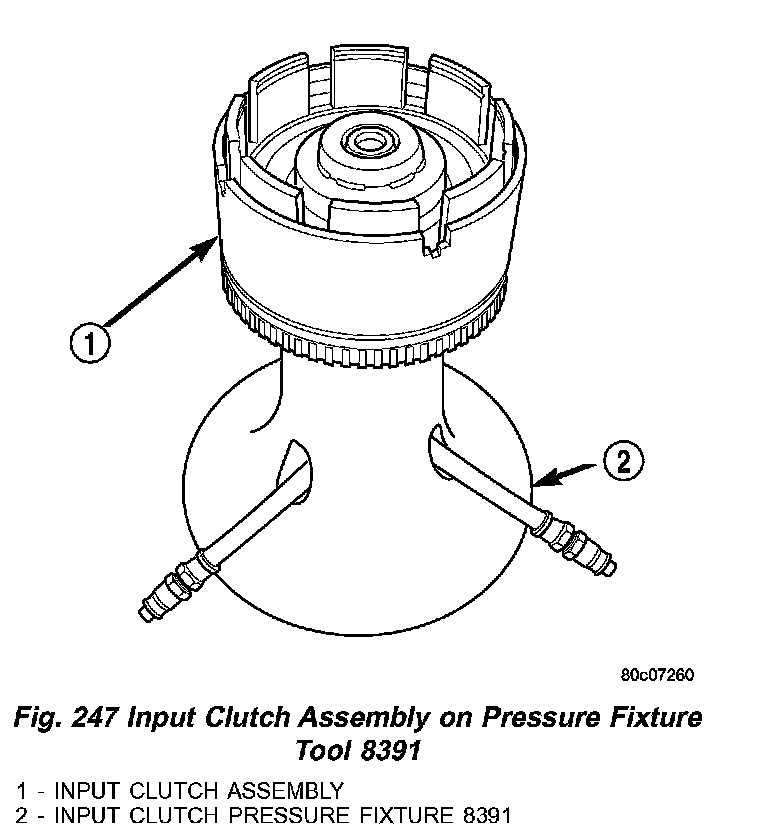
18) Install input clutch assembly (1) (Fig. 247) to the Input Clutch Pressure Fixture Tool 8391 (2).
Fig. 248 Set Up Dial Indicator to Measure UD ClutchClearance:
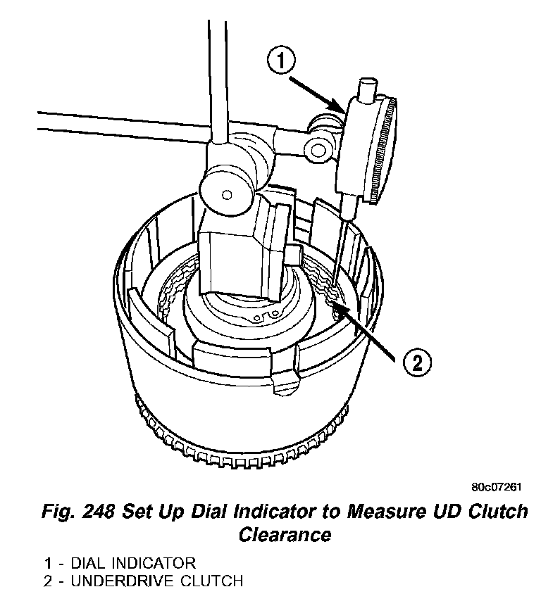
19) Set up dial indicator (1) (Fig. 248) on the UD clutch pack (2).
Fig. 249 Press Down on UD Clutch Pack and ZeroDial Indicator:
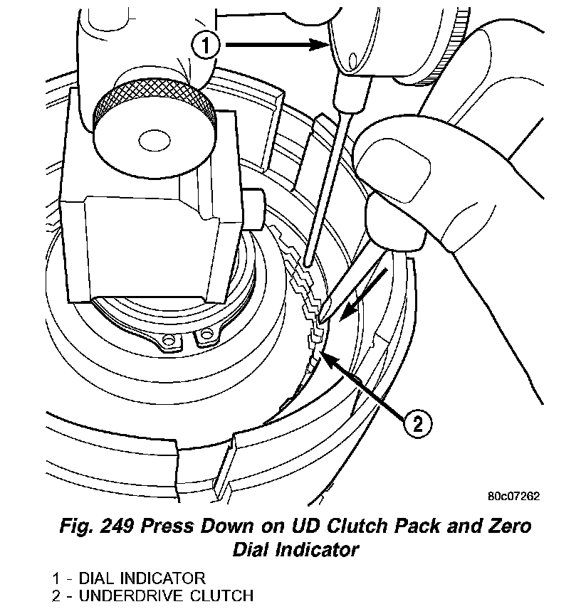
20) Using moderate pressure, press down and hold (near indicator) (1) (Fig. 249) the UD clutch pack (2) with screwdriver or suitable tool and zero dial indicator. When releasing pressure on clutch pack, indicator reading should advance 0.005 - 0.010 .
CAUTION: Do not apply more than 30 psi (0.06 kPa) to the underdrive clutch pack.
21) Apply 30 psi (0.06 kPa) to the underdrive hose on Tool 8391 and measure UD clutch clearance. Measure and record UD clutch pack measurement in four (4) places, 90° apart.
22) Take average of four measurements and compare with UD clutch pack clearance specification. Underdrive clutch pack clearance must be 0.94 - 1.50 mm (0.037 - 0.059 inch).
23) If necessary, select the proper reaction plate to achieve specifications:
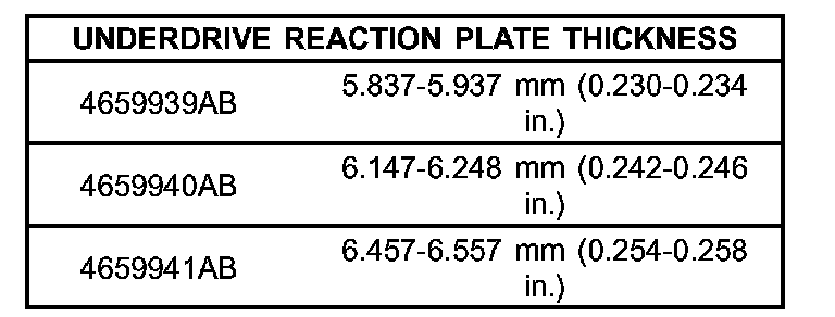
Fig. 250 Install Overdrive Clutch Pack:
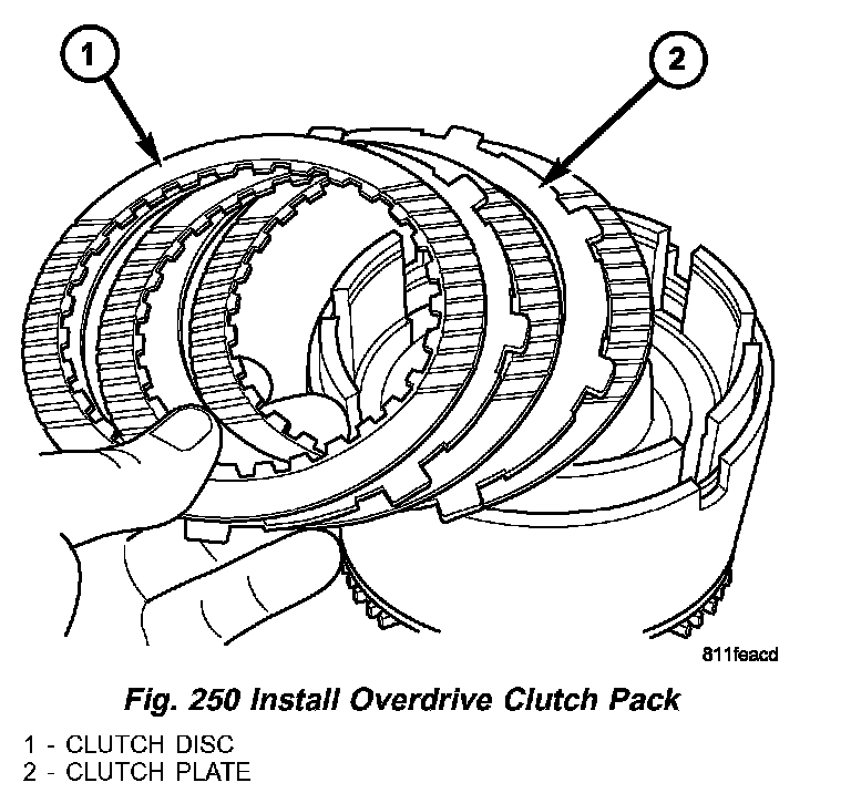
24) Install the OD clutch pack (1,2) (Fig. 250).
Fig. 251 Install Waved Snap Ring:
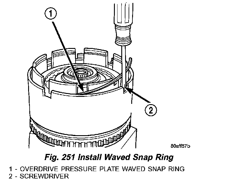
25) Install OD pressure plate waved snap ring (1) (Fig. 251) using a screwdriver (2).
Fig. 252 OD/Reverse Reaction Plate:
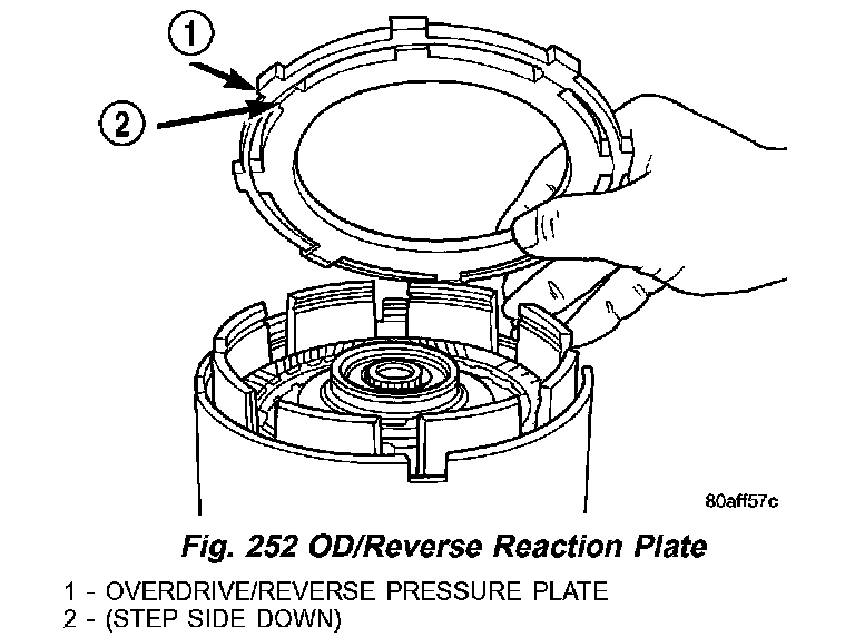
26) Install the OD/Reverse pressure plate (1) (Fig. 252) with large step down (towards OD clutch pack) (2).
Fig. 253 Overdrive Clutch Assembly:
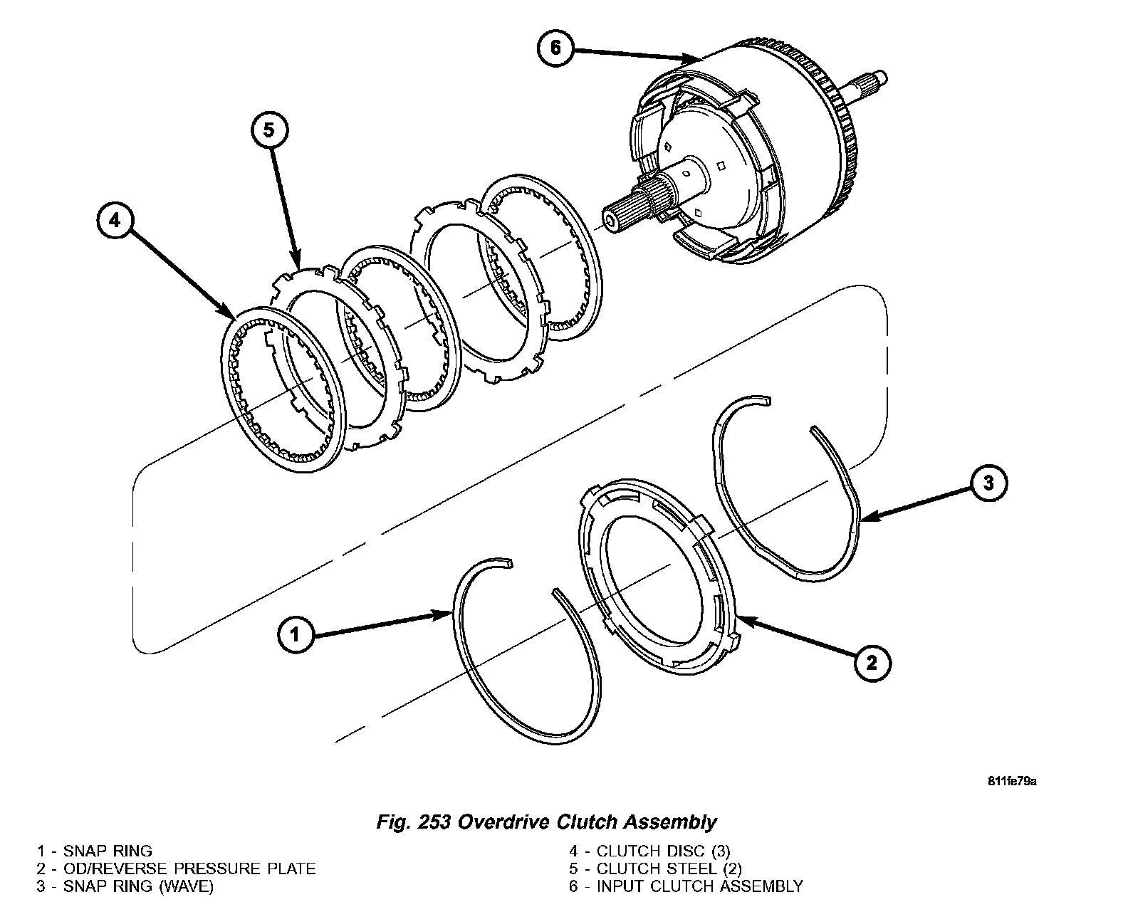
Refer to the exploded view (Fig. 253) as necessary when performing the following steps.
Fig. 254 Install Flat Snap Ring:
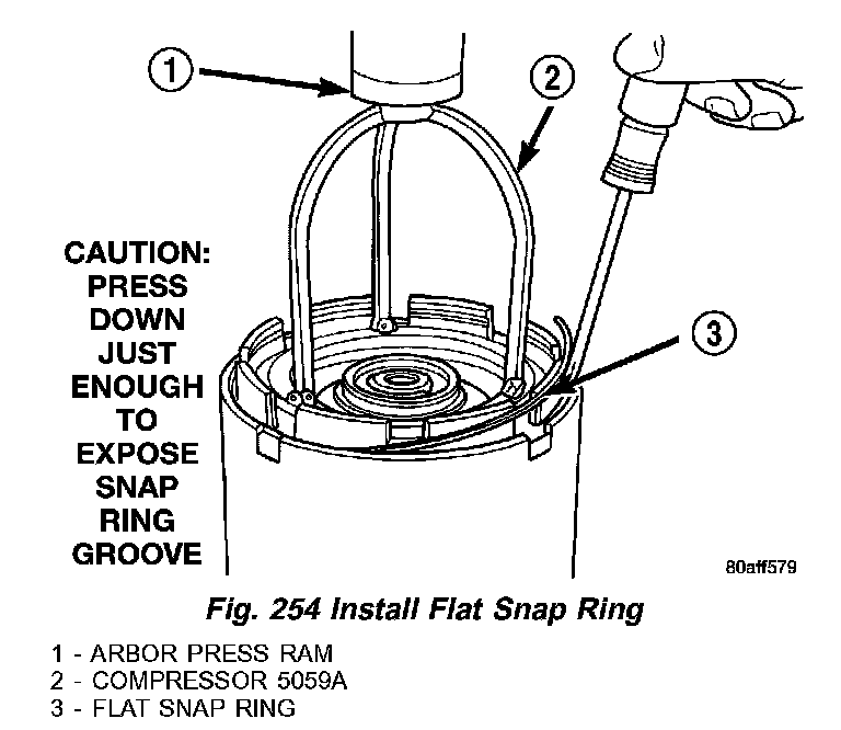
27) Install OD pressure plate flat snap ring (3) (Fig. 254) using Compressor 5059A (2) and an arbor press (1).
Fig. 255 Measure OD Clutch Pack Clearance:
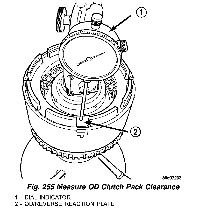
28) Measure OD clutch pack clearance. Set up dial indicator (1) (Fig. 255) on top of the OD/Reverse pressure plate (2).
29) Zero dial indicator and apply 30 psi (0.06 kPa) air pressure to the overdrive clutch hose on Input Clutch Pressure Fixture 8391. Measure and record OD clutch pack measurement in four (4)places, 90° apart.
30) Take average of four measurements and compare with OD clutch pack clearance specification.
The overdrive (OD) clutch pack clearance is 1.07 - 3.25 mm (0.042 - 0.128 inch).
If not within specifications, the clutch is not assembled properly. There is no adjustment for the OD clutch clearance.
Fig. 256 Install Reverse Clutch Pack:
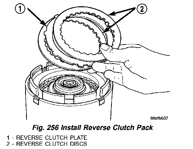
31) Install reverse clutch pack (two frictions/one steel) (1,2) (Fig. 256).
Fig. 257 Install Reaction Plate:
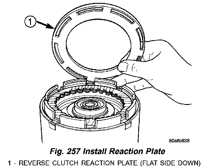
32) Install reverse clutch reaction plate with the flat side down towards reverse clutch (1) (Fig. 257).
Fig. 258 Reverse Clutch Assembly:
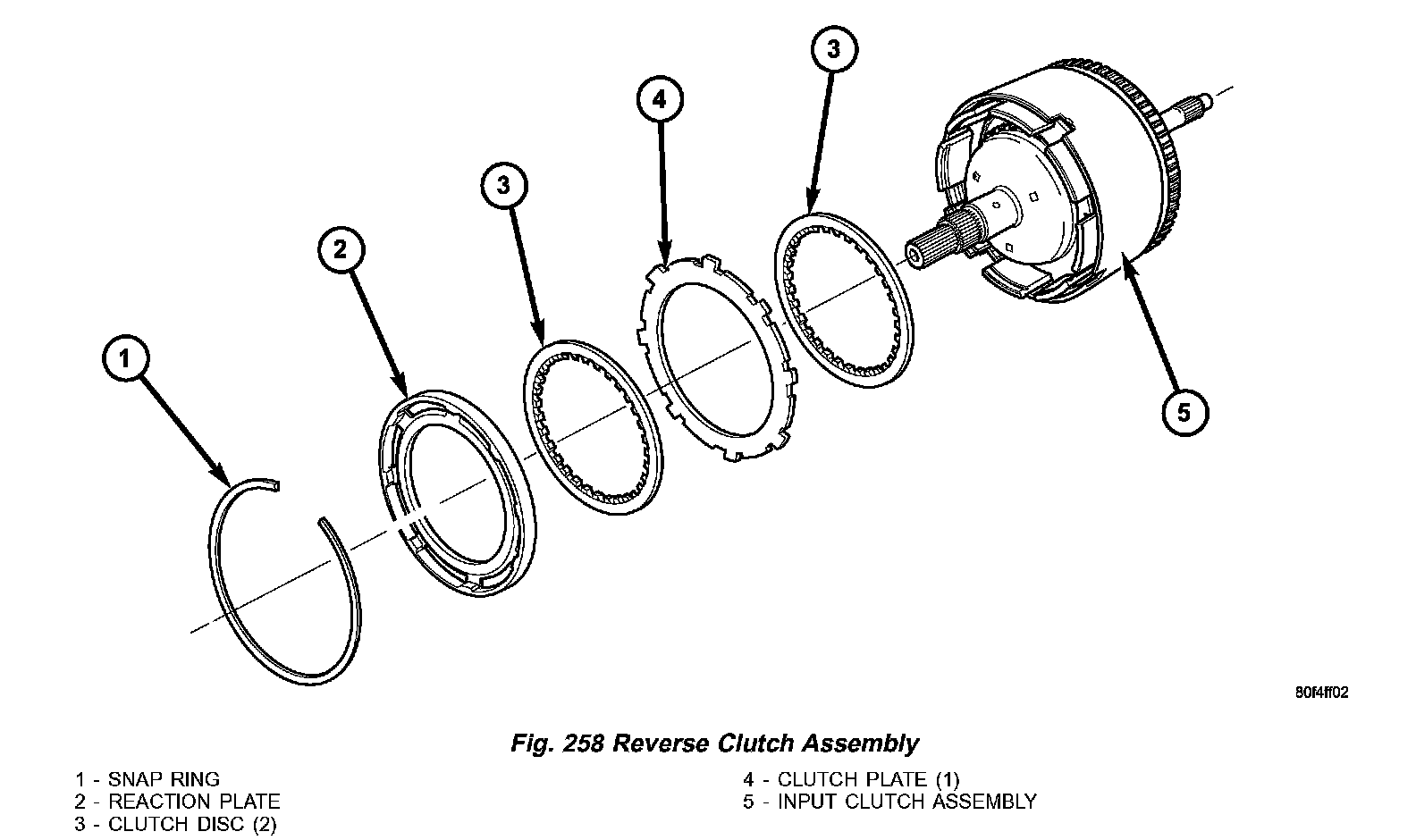
Refer to the exploded view (Fig. 258) as necessary when performing the following steps.
Fig. 259 Install Reverse Clutch Snap Ring:
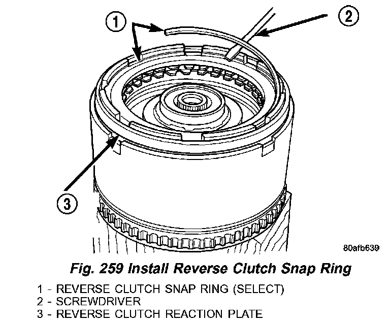
33) Tap reaction plate (3) (Fig. 259) down to allow installation of the reverse clutch snap ring (1). Install reverse clutch snap ring (1).
Fig. 260 Pry Up Reaction Plate:
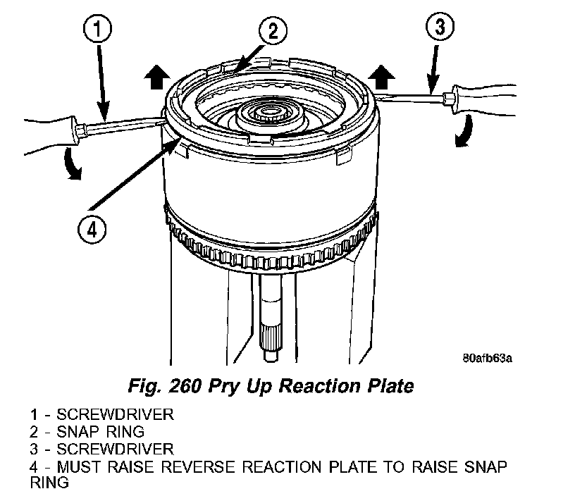
34) Pry up reverse reaction plate (1,3 and 4) (Fig. 260) to seat against snap ring (2).
Fig. 261 Measure Reverse Clutch Pack Clearance:
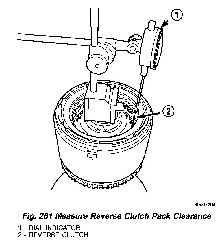
35) Set up a dial indicator (1) (Fig. 261) on the reverse clutch pack (2).
Fig. 262 Press Down on Reverse Clutch and ZeroIndicator:
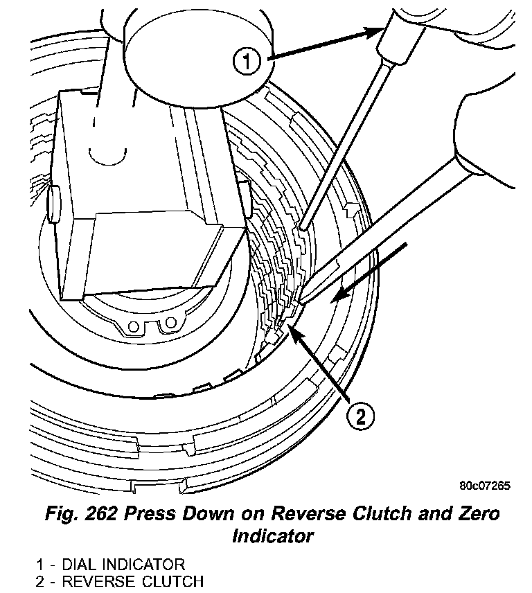
36) Using moderate pressure, press down and hold (near indicator) reverse clutch disc (2) (Fig. 262) with screwdriver or suitable tool and zero dial indicator (1). When releasing pressure, indicator should advance 0.005 - 0.010. as clutch pack relaxes.
37) Apply 30 psi (0.06 kPa) air pressure to the reverse clutch hose on Input Clutch Pressure Fixture 8391. Measure and record reverse clutch pack measurement in four (4)places, 90° apart.
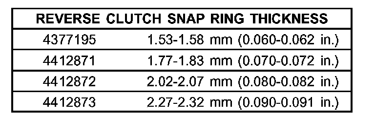
38) Take average of four measurements and compare with reverse clutch pack clearance specification. The reverse clutch pack clearance is 0.89 - 1.37 mm (0.035 - 0.054 inch). Select the proper reverse clutch snap ring to achieve specifications:
39) To complete the assembly, reverse clutch and overdrive clutch must be removed.
Fig. 263 Install No. 2 Needle Bearing:
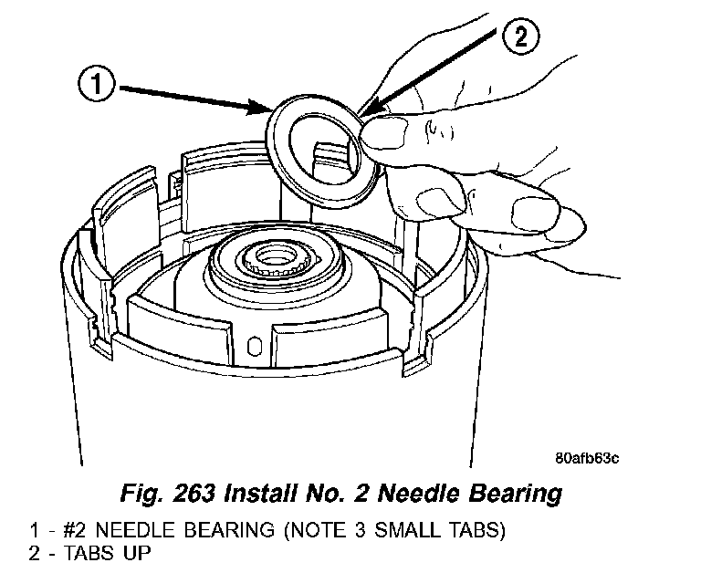
40) Install the #2 needle bearing (1) (Fig. 263) (tabs up) (2).
Fig. 264 Install Underdrive Shaft Assembly:
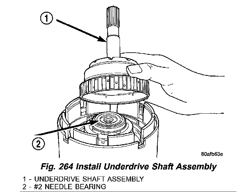
41) Install the underdrive shaft assembly (1) (Fig. 264).
Fig. 265 Install No. 3 Thrust Washer:
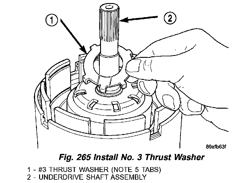
42) Install the #3 thrust washer (1) (Fig. 265) to the underdrive shaft assembly (2). Be sure five tabs are seated properly.
Fig. 266 Install No. 3 Thrust Plate:
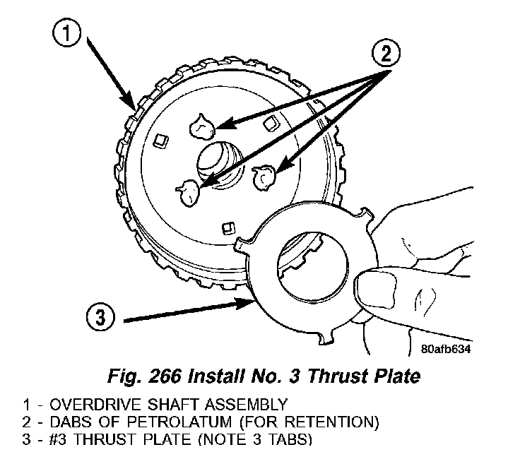
43) Install the #3 thrust plate (note 3 tabs) (3) (Fig. 266) to the bottom of the overdrive shaft assembly (1). Retain with petrolatum or transmission assembly gel (2).
Fig. 267 Underdrive Clutch Assembly:
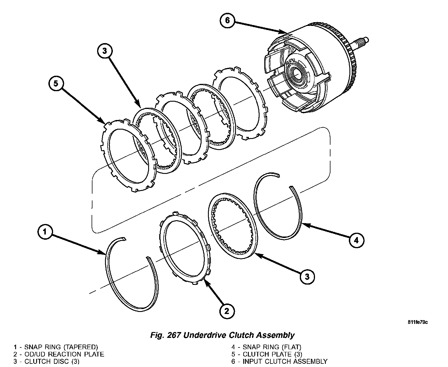
Refer to the exploded view (Fig. 267) as necessary when performing the following steps.
Fig. 268 Install Overdrive Shaft Assembly:
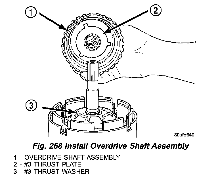
44) Install the overdrive shaft assembly (Fig. 268).
45) Reinstall overdrive and reverse clutch as shown. Rechecking these clutch clearances is not necessary.