Service Procedure
1. Open the hood and disconnect the negative battery cable.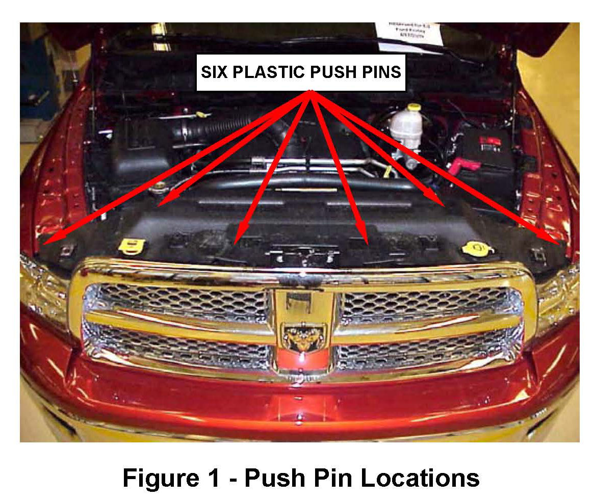
2. Remove and save the six radiator close out panel plastic push pins (Figure 1).
3. Remove the radiator close out panel.
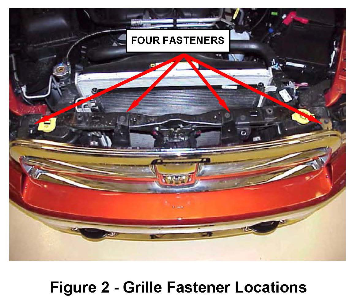
4. Remove the four upper grille fasteners (Figure 2).
5. Carefully remove the grille by pulling forward on the lower grille section to release the lower grille tabs.
6. Partially remove the washer fluid reservoir from the radiator core support using the following procedure:
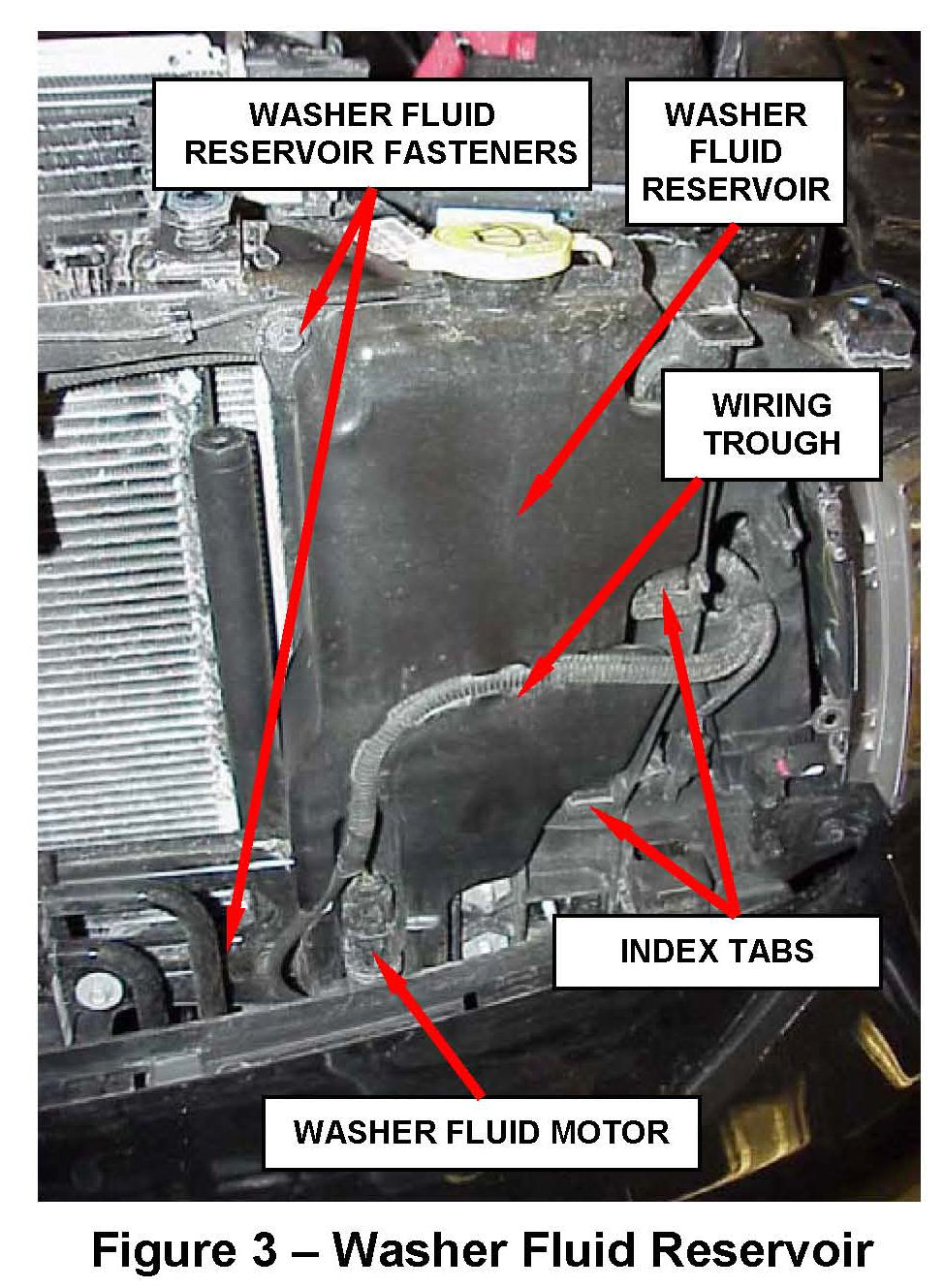
a. Remove the wiring harness from the front of the washer fluid reservoir trough (Figure 3).
b. Disconnect the electrical connector from the washer fluid motor (Figure 3).
c. Remove the two washer fluid reservoir fasteners (Figure 3).
d. Lift the washer fluid reservoir to disconnect the two index tabs from the radiator core support (Figure 3)
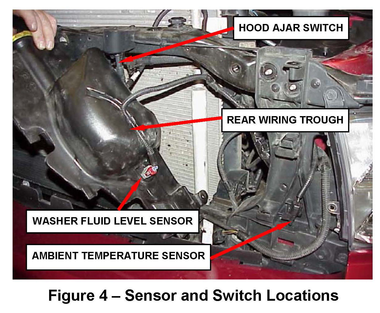
7. Remove the wiring harness from the rear of the washer fluid reservoir trough and lay the reservoir on its side (Figure 4).
8. Disconnect the electrical connectors from the washer fluid level sensor, ambient temperature sensor and the hood ajar switch (if equipped) (Figure 4).
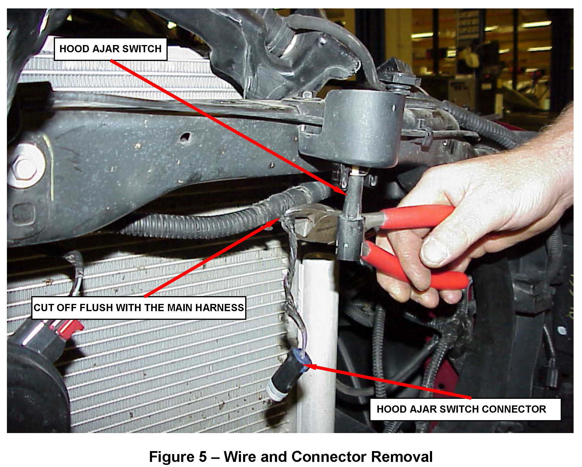
9. Using diagonal cutters, cut off the wires that were removed from the washer fluid level sensor, ambient temperature sensor and hood ajar switch (if equipped) flush with the main wiring harness (Figure 5).
NOTE:
The new overlay harness has new connectors and wiring for these components.
10. Wrap the main wiring harness with electrical tape where the three electrical connectors were cut off.
11. Replace the ambient temperature sensor with the supplied sensor (Figure 4).
12. Replace the washer fluid level sensor and grommet with the supplied sensor and grommet (Figure 4).
NOTE:
Lube both the washer fluid level sensor and grommet with washer fluid prior to installation.
13. Install the supplied overlay wiring harness.
> Vehicles without hood ajar switch, continue with Step 14.
> Vehicles with hood ajar switch, continue with Step 17.
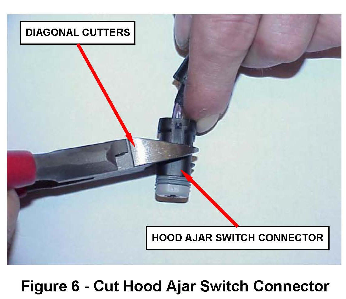
14. Locate the hood ajar switch connector on the supplied overlay wiring harness. Using diagonal cutters, cut the hood ajar switch connector in half (Figure 6).
15. Remove the wires from the wire side of the hood ajar connector.
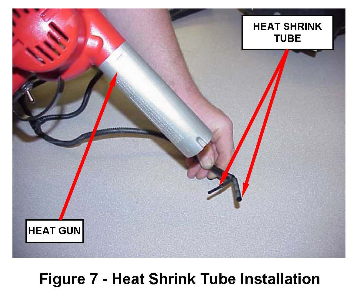
16. Place a piece of heat shrink tube over each individual wire end and heat the shrink tube until glue comes out of both ends of the shrink tube (Figure 7).
17. Connect the supplied overlay wiring harness to the washer fluid level sensor, hood ajar switch (if equipped) and ambient temperature sensor. The wiring for the ambient temperature sensor must be routed through the opening in the core support (Figure 8).
18. Attach the overlay wiring harness to the main harness using three of the supplied tie wraps (Figure 8).
19. Position the overlay wiring harness in the wiring trough at the rear of the washer fluid reservoir (Figure 4).
20. Position the two washer fluid reservoir tabs over the two slots in the core support and apply downward pressure to seat the washer fluid reservoir (Figure 3). Install the two washer fluid reservoir fasteners and tighten to 53 in. lbs. (6 N.m).
21. Position the washer fluid motor wiring in the wiring trough at the front of the washer fluid reservoir and connect the washer fluid motor electrical connector (Figure 3).
22. Partially remove the Totally Integrated Power Module (TIPM) using the following procedure:
a. Open the cover of the TIPM.
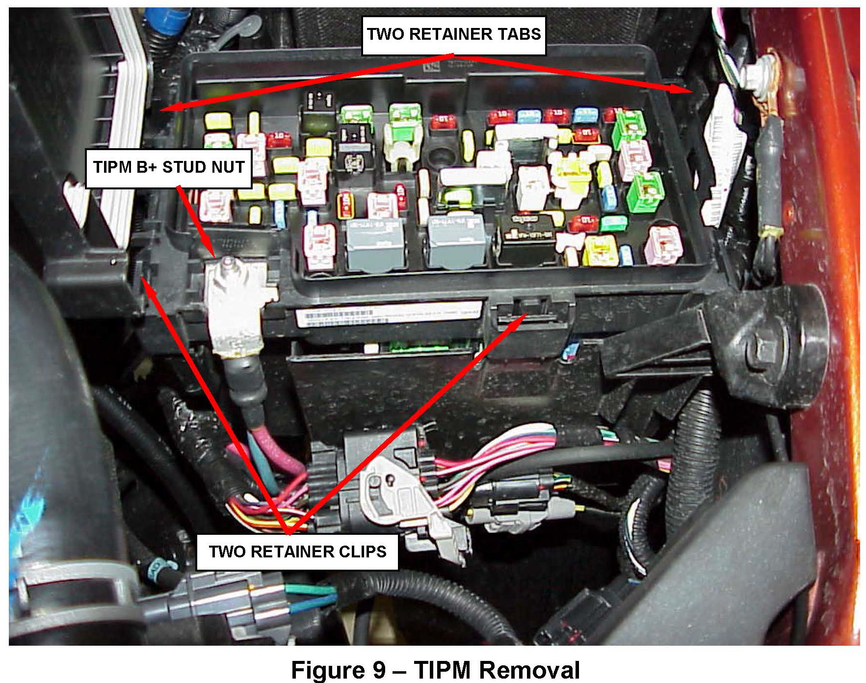
b. Remove the nut from the TIPM B+ terminal stud (Figure 9).
c. Remove the battery positive cable from the TIPM B+ terminal stud.
d. Using a suitable flat bladed tool, depress the two retainer clips and with your fingers depress the two retainer tabs, then lift the TIPM straight up off of the bracket tabs (Figure 9).
e. Lay the TIPM on its side to expose the electrical connectors on the bottom of the TIPM.
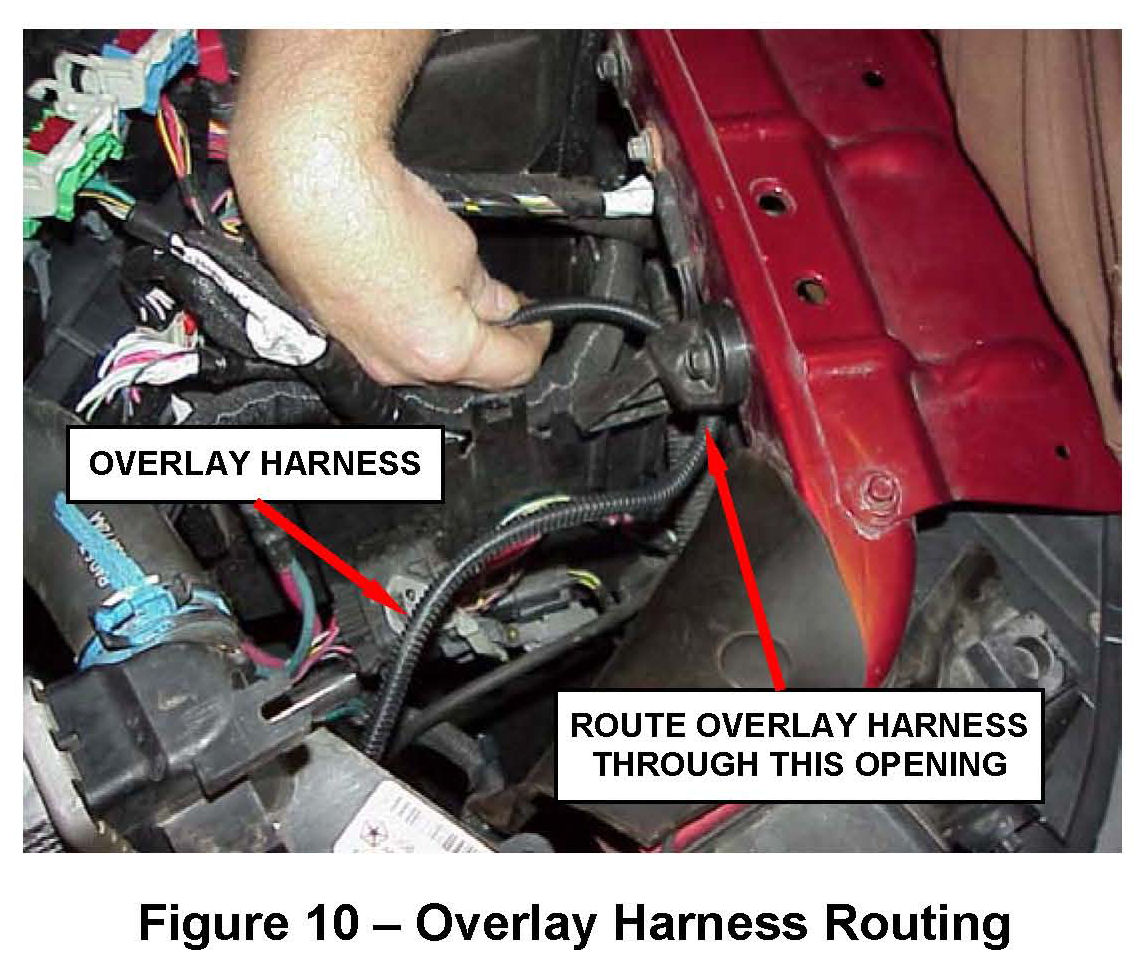
23. Route the terminal end of the overlay wiring harness through the opening between the inner fender support and the TIPM lower housing (Figure 10).
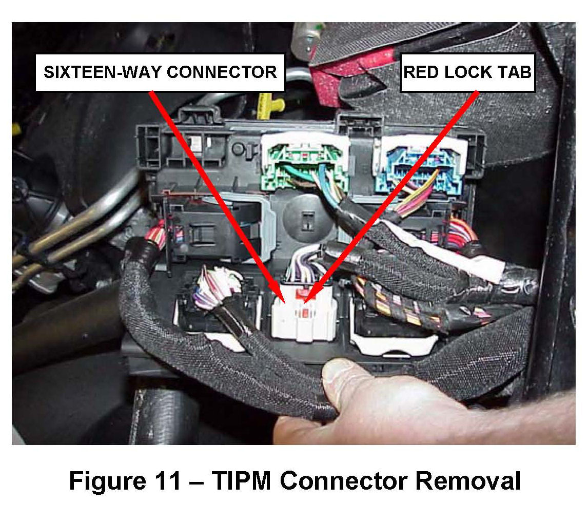
24. Disconnect the sixteen-way gray electrical connector from cavity "D" on the TIPM by first sliding the red lock tab in the direction of the wiring harness. Then push down on the release tab while pulling the connector from the TIPM (Figure 11).
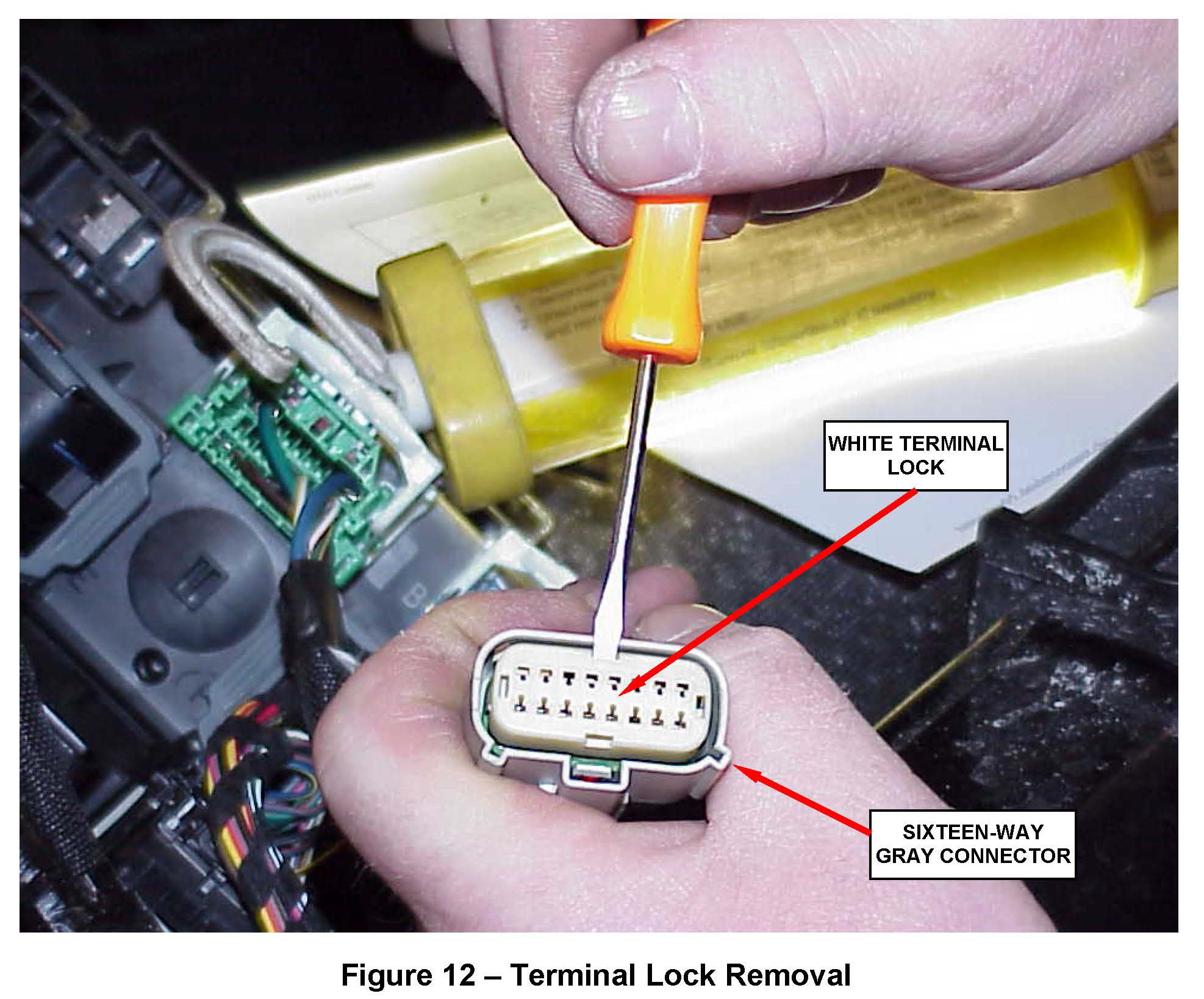
25. Remove the white terminal lock from the sixteen-way gray electrical connector (Figure 12).
26. The wire terminals in cavities 3, 10, 14, and 15 must be removed from the sixteen-way connector. They will be replaced with the four corresponding wires of the overlay wiring harness using the following procedure:
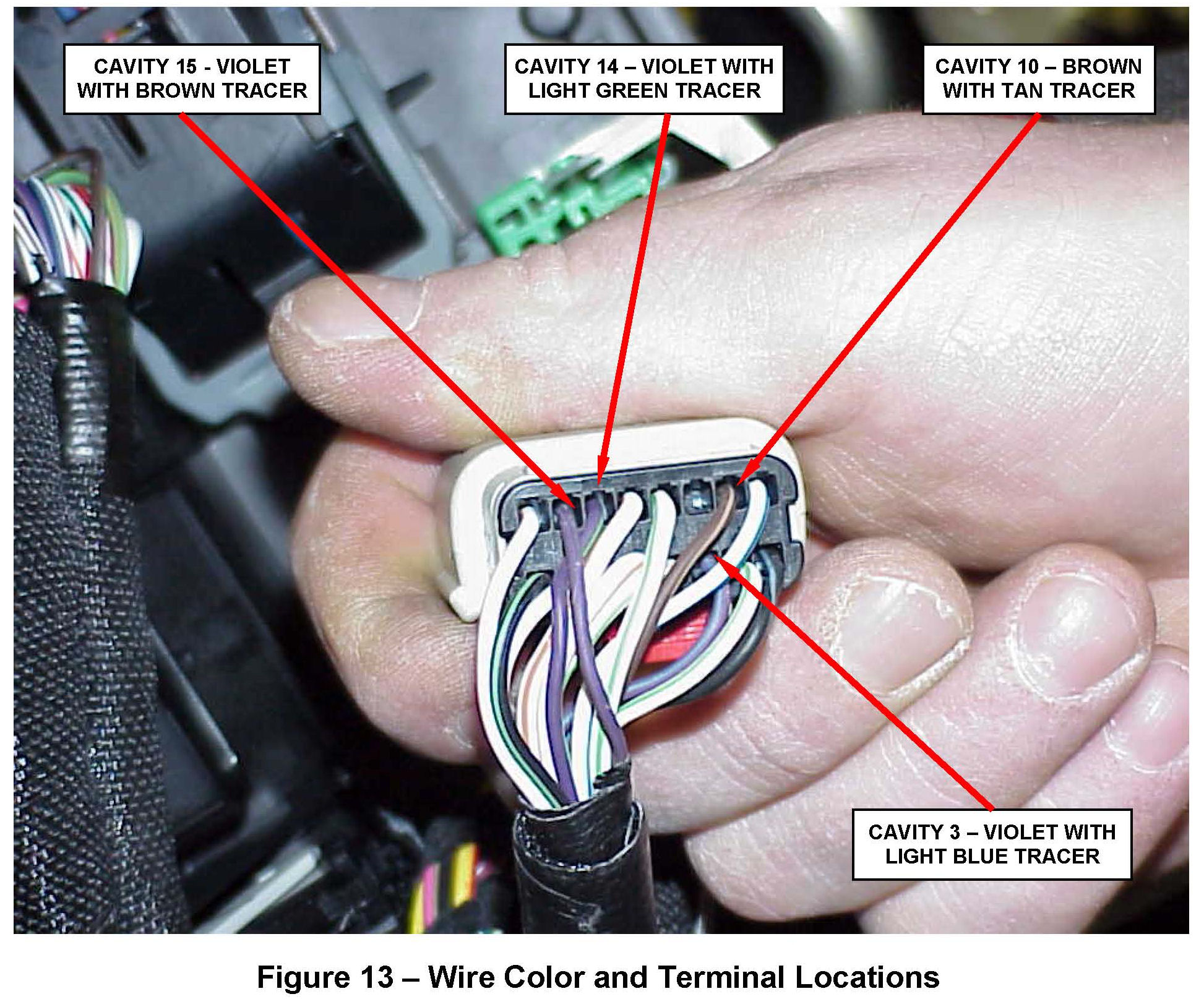
a. From the wire side of the connector identify the four wires that require replacement (Figure 13).
b. From the terminal side of the connector, insert a small pick into the connector next to one of the identified wire terminals and push on the terminal release arm while pulling on the wire.
CAUTION:
Remove only one wire from the sixteen-way connector at a time.
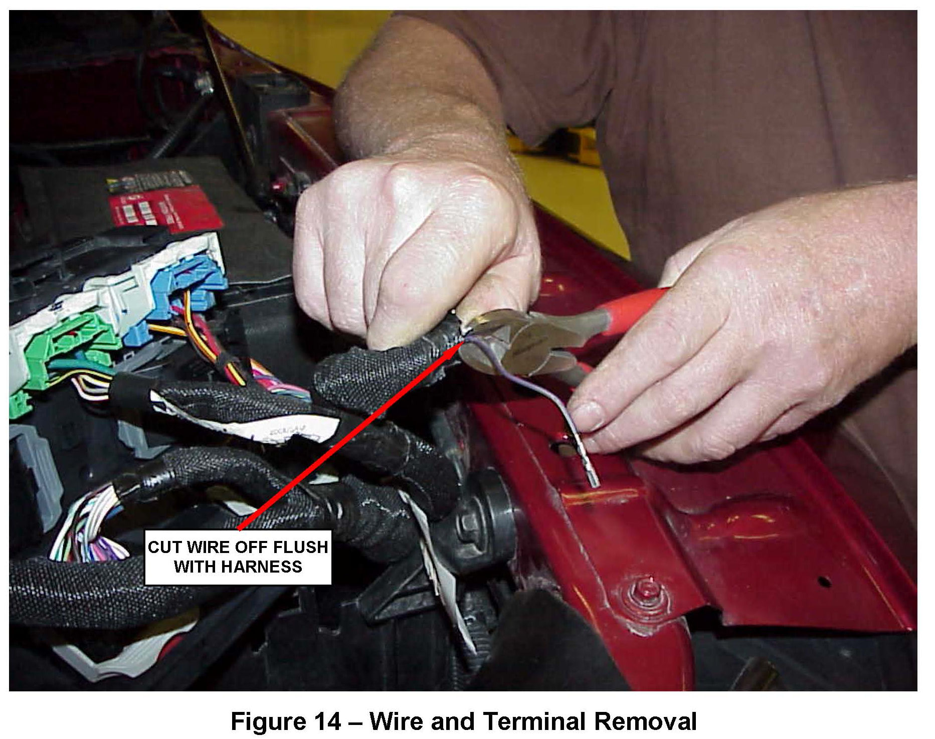
c. Using diagonal cutters, cut off the wire that was removed from the sixteen-way connector flush to the main wiring harness (Figure 14).
d. Insert the corresponding wire terminal from the overlay wiring harness into the sixteen-way connector that the wire terminal was just removed from.
e. Repeat Steps 22 a. through 22 d. on the remaining three wires that require replacement with the overlay wiring harness.
27. After all four wire terminals have been replaced, install the white terminal lock into the sixteen-way connector (Figure 12).
28. Wrap the main wiring harness with electrical tape where the four connector wires were cut off.
29. Connect the sixteen-way connector to cavity "D" of the TIPM and slide the red locking tab in the direction opposite the wiring harness (Figure 11).
30. Position the TIPM over the four bracket tabs and apply downward pressure until the retaining clips snap securely into position (Figure 9).
31. Connect the battery positive cable to the TIPM B+ terminal stud.
32. Install the TIPM B+ terminal stud nut (Figure 9). Tighten the nut to 133 in. lbs. (15 N.m).
33. Close the TIPM cover ensuring the locking tabs snap firmly in place.
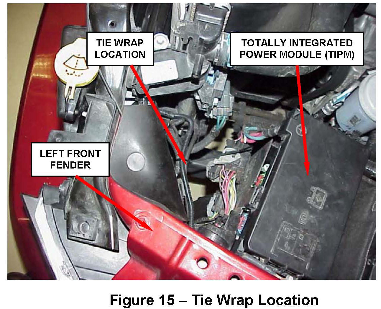
34. Attach the overlay wiring harness to the main harness at the front side of the TIPM using the supplied tie wrap (Figure 15).
35. Connect the negative battery cable.
36. Top off the washer fluid reservoir with fluid and verify there are no leaks.
37. Install the grille by aligning the four lower tabs into the retainer brackets and apply rearward pressure until the tabs snap firmly in place.
38. Install the four upper grille fasteners (Figure 2).
39. Position the radiator close out panel and install the six plastic push pins (Figure 1).