40 Percent
FRONT SEAT BACKREST - 40 PERCENTSpecial Tool(s):

SPECIAL TOOL(S)
DISASSEMBLY
WARNING: The safety belt pretensioner is a pyrotechnic device. Always wear safety glasses when repairing an air bag equipped vehicle and when handling a safety belt buckle pretensioner or safety belt retractor pretensioner. Never probe pretensioner electrical connectors. Doing so could result in pretensioner or air bag deployment and could result in personal injury.
All vehicles
1. WARNING: To avoid accidental deployment and possible personal injury, the backup power supply must be depleted before repairing or replacing any front or side air bag supplemental restraint system (SRS) components and before servicing, replacing, adjusting or striking components near the front or side air bag sensors, such as doors, instrument panel, console, door latches, strikers, seats and hood latches.
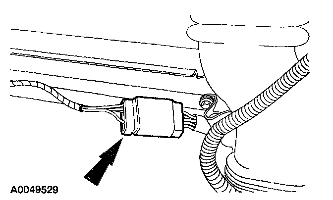
The front impact severity sensor is located at the bottom of the hood latch support bracket.
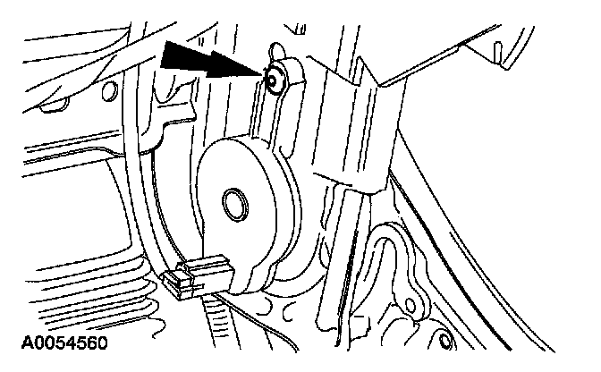
The first row side impact sensors (if equipped) are located in the first row doors, behind the door trim panel.
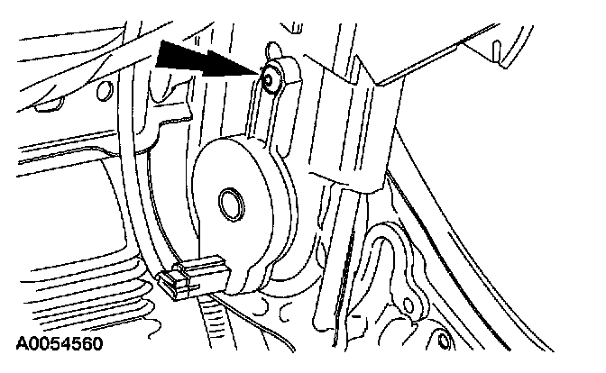
The second row side impact sensors (if equipped) are located at or near the base of the C-pillars.
To deplete the backup power supply energy, disconnect the battery ground cable and wait at least one minute. Be sure to disconnect auxiliary batteries and power supplies (if equipped).
Disconnect the battery ground cable and wait at least one minute.
2. WARNING: To reduce the risk of serious personal injury, read and follow all warnings, cautions, notes, and instructions in the supplemental restraint system (SRS) deactivation/reactivation procedure.
Deactivate the supplemental restraint system (SRS).
3. WARNING: To reduce the risk of serious personal injury, read and follow all warnings, cautions, notes and instructions in the front seat removal and installation procedure.
Remove the 40 percent seat.

4. Remove lower seat backrest cover.
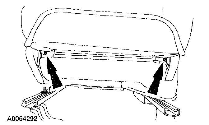
5. Remove the two screws from the support rod.

6. Release the one hook-and-loop strip and the one J-clip.
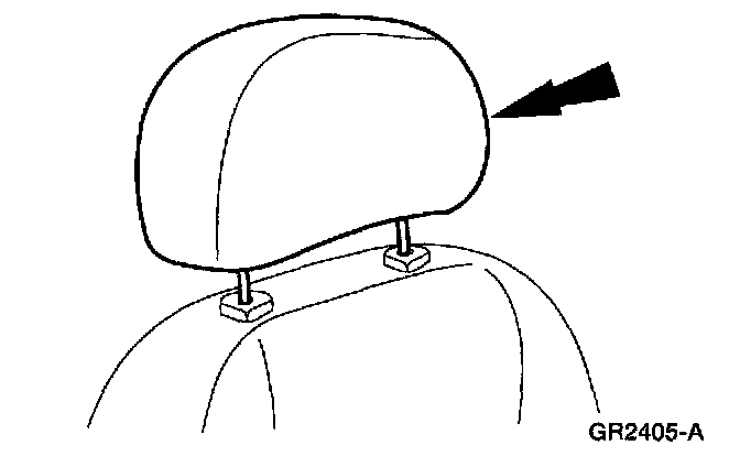
7. Depress tab and remove the head restraint.
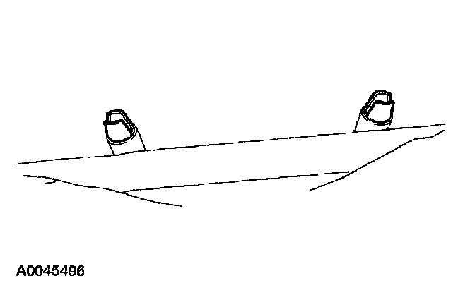
8. NOTE: The head restraint sleeve pins are not interchangeable. Note location for installation.
Reach up into seat backrest and squeeze the head restraint sleeve ends together to release the sleeves and pull the head restraint sleeves out.
9. CAUTION: Use care when separating the seat backrest trim cover from the hook-and-loop strip, or the hook-and-loop strip can be torn from the seat backrest foam.
Invert the seat backrest trim cover and remove.
Vehicles with temperature controlled seats

10. CAUTION: Use care when removing the seat backrest foam pad from the frame. The foam pad has hook and loop fasteners holding the thermo-electric device (TED) to the seat backrest foam pad.
Remove the seat backrest foam pad from the thermo-electric device (TED).

11. Disconnect the seat backrest TED electrical connector.
All vehicles
12. Remove the seat backrest foam pad from the frame.
Vehicles with manual lumbar

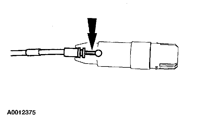
13. NOTE: The lumbar support assembly must be fully relaxed.
Separate the adjuster cable from the lumbar support adjuster.
Vehicles with power lumbar

14. Remove the staples and open dampening bag.

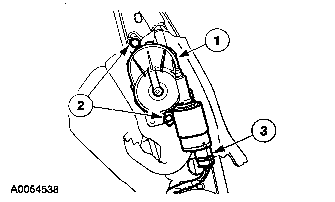
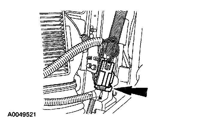
15. Remove the power lumbar support motor.
1 Disconnect the power lumbar motor electrical connector.
2 Remove the screws.
3 Remove the power lumbar support motor.
All vehicles

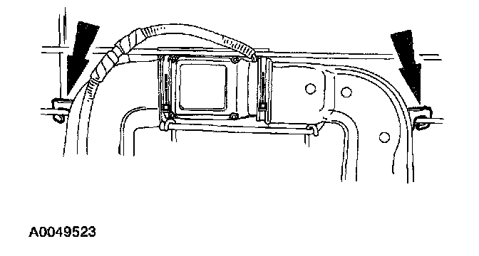
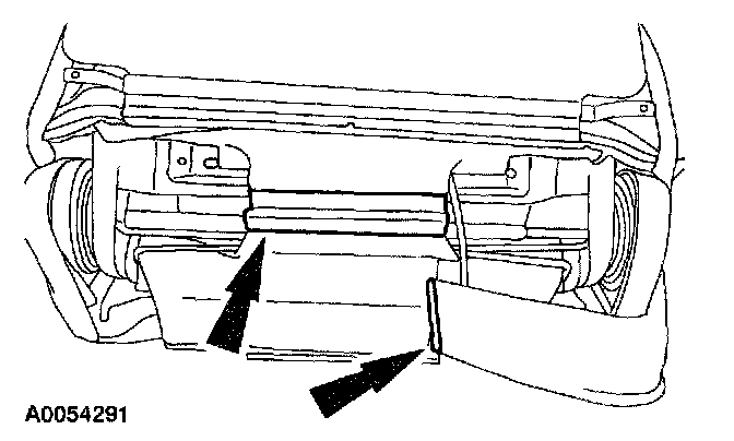
16. Remove the screws from the two support covers (one side shown) and remove support covers (two shown).

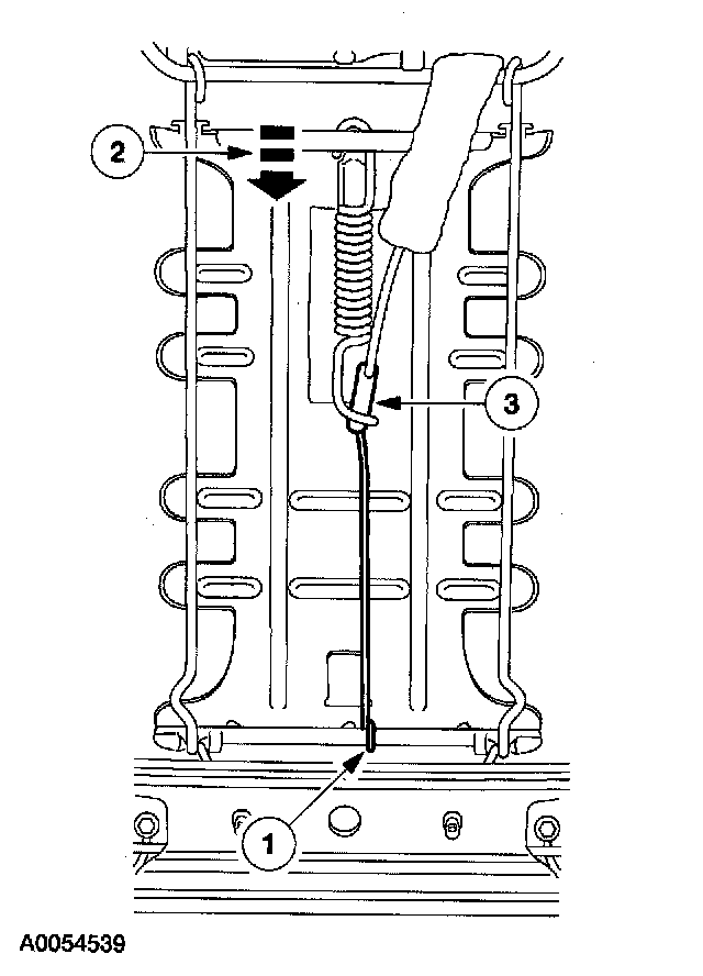
17. Remove the lumbar motor cable from the lumbar support.
1 Flex the lumbar support.
2 Separate the lumbar support adjusting cable from the positioning spring.
3 Unhook the lumbar support adjusting cable from the lumbar support.

18. Remove the lumbar support.
1 Remove the pin-type retainers.
2 Unhook the upper lumbar support bracket.
Vehicles with temperature controlled seats

19. Remove the screw at bottom of the two TED ducts (one shown).
20. Unhook the TED and ducts from support rod.
Vehicles with power recliner

21. Remove the retainer clip on the end of power recliner motor shaft.

22. Remove the power recliner motor shaft.
1 Remove the power recliner motor shaft cover.
2 Slide the power recliner motor shaft out from the power recliner motor.

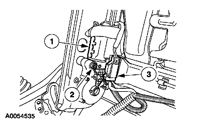
23. Remove power recliner motor.
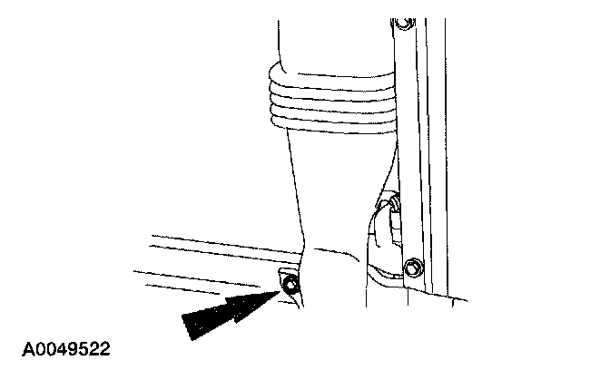
1 Disconnect the power recliner motor electrical connector.
2 Remove the power recliner motor bolt.
3 Remove the power recliner motor.
24. Disconnect the power recliner position sensor electrical connector.
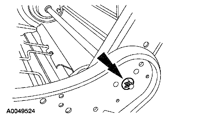
25. CAUTION: Make sure to remove all the rivet metal chips from sensor and surrounding areas.
Remove the rivet and remove the power recliner position sensor.
ASSEMBLY
WARNING: To reduce the risk of serious personal injury, read and follow all warnings, cautions, and notes at the beginning of the removal procedure.
Vehicles with power recliner
1. CAUTION: Make sure to remove all the rivet metal chips from sensor and surrounding areas.
Install the power recliner position sensor and install the rivet.

2. Connect the power recliner position sensor electrical connector.
3. Install the power recliner motor.
1 Install the power recliner motor.
2 Install the power recliner motor bolt.
3 Connect the power recliner motor electrical connector.

4. Install the power recliner shaft.
1 Slide the power recliner shaft into the motor and through the seat.
2 Install the power recliner shaft cover.
5. Install the retainer clip on end of power recliner shaft.
Vehicles with temperature controlled seats

6. Install the TED and ducts on support rod.
7. Install the screw at the bottom of the two TED ducts (one shown).
All vehicles

8. Install the lumbar support.
1 Hook the upper lumbar support bracket.
2 Install the pin-type retainers.
9. NOTE: The lumbar support assembly must be fully relaxed.
Install the lumbar motor cable to the lumbar support.
1 Hook the lumbar support adjusting cable to the lumbar support.
2 Flex the lumbar support.
3 Install the lumbar support adjusting cable to the positioning spring.
Vehicles with power lumbar
10. Install the power lumbar support motor.
1 Install the power lumbar support motor.
2 Install the screws.
3 Connect the power lumbar electrical connector.

11. Close the dampening bag and staple.
Vehicles with manual lumbar
12. NOTE: The lumbar support assembly must be fully relaxed.
Install the adjuster cable to the lumbar support adjuster.
All vehicles
13. Install the seat backrest foam pad.
Vehicles with temperature controlled seats

14. Attach the seat backrest TED to the foam pad.
15. Connect the seat backrest TED electrical connector.
All vehicles

16. Install the two support covers and install the screws for the support covers (one side shown).
17. Install the seat backrest trim cover and attach the hook-and-loop fasteners.

18. NOTE: The head restraint sleeve pins are not interchangeable.
Install the head restraint sleeves.

19. Install the head restraint.
20. Connect the one hook-and-loop strip and the one J-clip.

21. Install the two screws in the support rod.

22. Install the lower backrest cover.
23. WARNING: To reduce the risk of serious personal injury, read and follow all warnings, cautions, notes and instructions in the front seat removal and installation procedure.
Install the 40 percent seat.
24. WARNING: To reduce the risk of serious personal injury, read and follow all warnings, cautions, notes and instructions in the supplemental restraint system (SRS) deactivation/reactivation procedure.
Reactivate the supplemental restraint system (SRS).
25. WARNING: The restraint system diagnostic tool is for restraint system service only. Remove from the vehicle prior to road use. Failure to remove could result in injury and possible violation of vehicle safety standards.
With all the restraint system diagnostic tools removed, prove out the supplemental restraint system (SRS).