Part 1 of 2
Cylinder Heads-5.4L


Special Tool(s)
Installation

All cylinder heads
1. CAUTION: The gasket sealing surfaces on the cylinder head and cylinder block must be clean.
CAUTION: The use of sealing aids (aviation cement, copper spray, and glue) is not permitted. The gasket must be installed dry.
CAUTION: The new gasket has a film coating which is crucial to the gasket's ability to seal correctly Do not scratch the gasket.
NOTE: The RH head gasket is shown; the LH head gasket is similar
Install the head gasket over the dowel pins

2. CAUTION: Cylinder head machining or milling is not authorized by the Ford Motor Company. Cylinder head flatness must be within 0.0254 mm (0.001 inch) across a 38.1 mm (1.5 inch) square area.
CAUTION: The gasket sealing surfaces on the cylinder head and cylinder block must be clean.
CAUTION: The use of sealing aids (aviation cement, copper spray, and glue) is not permitted. The gasket must be installed dry.
CAUTION: Do not allow the dowels to scratch the sealing surface of the cylinder head during cylinder head installation.
NOTE: The new cylinder head bolts must be lightly oiled with a rag and allowed to drain for a few minutes prior to installation.
NOTE: The RH cylinder head is shown; the LH cylinder head is similar.
Install the cylinder head on the dowels and the head gasket. Loosely install new bolts.

LH cylinder head
3. NOTE: Make sure to tighten the bolts in sequence in three stages.
Tighten the LH bolts in the sequence shown.
^ Stage 1: Tighten to 40 Nm (30 ft. lbs.).
^ Stage 2: Tighten an additional 90 degrees.
^ Stage 3: Tighten an additional 90 degrees.

RH cylinder head
4. NOTE: Make sure to tighten the bolts in the following three stages.
Tighten the RH bolts in the sequence shown.
^ Stage 1: Tighten to 40 Nm (30 ft. lbs.).
^ Stage 2: Tighten an additional 90 degrees.
^ Stage 3: Tighten an additional 90 degrees.

All cylinder heads
5. Remove the special tools from both ends of the cylinder head.

6. NOTE: Lubricate the hydraulic lash adjusters with clean engine oil.
Install the hydraulic lash adjusters in their original locations.

RH cylinder head
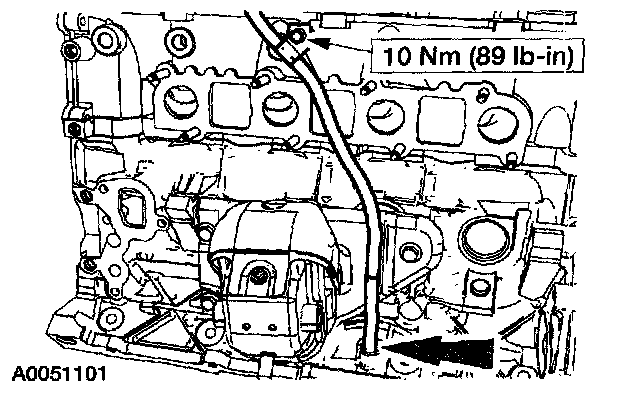
7. Position the RH exhaust manifold gasket and the exhaust manifold. Loosely install the nuts.

8. Tighten the RH exhaust manifold nuts in the sequence shown.
LH cylinder head
9. NOTE: Lubricate the O-ring seal with clean engine oil.
Install the oil level indicator tube.
^ Install a new O-ring seal on the oil level indicator tube.
^ Install the oil level indicator tube.
^ Install the bolt.

10. Position the LH exhaust manifold gaskets and the exhaust manifold. Loosely install the nuts.

11. Tighten the LH exhaust manifold nuts in the sequence shown.

12. Install the heat shield and bolts.

All cylinder heads
13. CAUTION: Timing chain procedures must be followed exactly or damage to valves and pistons will result.
Compress the tensioner plunger, using a vise.

14. Install a retaining clip on the tensioner to hold the plunger in during installation.
15. Remove the tensioner from the vise.

16. If the copper links are not visible, mark two links on one end and one link on the other end, and use as timing marks.

17. Install the timing chain guides.

18. Pre-position the camshafts.
1 Rotate the LH camshaft until the timing mark is approximately at 12 o'clock.
2 Rotate the RH camshaft until the timing mark is approximately at 11 o'clock.

19. CAUTION: Rotate the crankshaft counterclockwise only. Do not rotate past position shown or severe piston and valve damage can occur.
NOTE: The number one piston is at Top Dead Center (TDC) when the stud on the engine block fits into the slot in the handle of the special tool.
Position the crankshaft so the number one cylinder is at TDC with the special tool.
20. Remove the Crankshaft Holding Tool.

21. Install the crankshaft sprocket, making sure the flange faces forward.

22. Position the lower end of the LH (inner) timing chain on the crankshaft sprocket, aligning the timing mark on the outer flange of the crankshaft sprocket with the single copper (marked) link on the chain.

23. NOTE: Make sure the upper half of the timing chain is below the tensioner arm dowel.
Position the timing chain on the camshaft sprocket with the camshaft sprocket timing mark positioned between the two copper (marked) chain links.

24. NOTE: The LH timing chain tensioner arm has a bump near the dowel hole for identification.
Position the LH timing chain tensioner arm on the dowel pin and install the LH timing chain tensioner.

25. Remove the retaining clip from the LH timing chain tensioner.

26. Position the lower end of the RH (outer) timing chain on the crankshaft sprocket, aligning the timing mark on the sprocket with the single copper (marked) chain link.

27. NOTE: The lower half of the timing chain must be positioned above the tensioner arm dowel.
Position the RH timing chain on the camshaft sprocket. Make sure the camshaft sprocket timing mark is positioned between the two copper (marked) chain links.

28. Position the RH timing chain tensioner arm on the dowel pin and install the RH timing chain tensioner.

29. Remove the retaining clip from the RH timing chain tensioner.

30. As a post-check, verify correct alignment of all timing marks.

31. Install the special tool between the valve spring coils to prevent valve stem seal damage.

32. NOTE: Lubricate the camshaft roller followers using clean engine oil.
NOTE: Position the cam lobe away from the camshaft roller follower location prior to installing each camshaft roller follower.
Install the camshaft roller followers.
1 Install the special tool.
2 Compress the valve spring.
3 Install the camshaft roller followers in their original locations.