Part 2 of 2
Cylinder Heads-5.4L Continued
33. Remove the special tool.
34. CAUTION: When installing the spark plugs, use care not to exceed the recommended torque.
Install the eight spark plugs.
^ Tighten the spark plugs to 18 Nm (13 ft. lbs.).

35. Install the crankshaft sensor ring on the crankshaft.

36. NOTE: If the front cover is not secured within four minutes, the sealant must be removed and the sealing area cleaned. To clean the sealing area, use silicone gasket remover and metal surface prep. Follow the directions on the packaging. Failure to follow this procedure can cause future oil leakage.
Apply a bead of silicone gasket and sealant along the cylinder head-to-cylinder block surface and the oil pan-to-cylinder block surface, at the locations shown.

37. Install a new engine front cover gasket on the engine front cover. Position the engine front cover. Install the fasteners finger-tight.


38. Tighten the engine front cover fasteners in sequence in three stages.
Stage 1: Tighten fasteners 1 through 5 to 25 Nm (18 ft. lbs.).
Stage 2: Tighten fasteners 6 and 7 to 48 Nm (35 ft. lbs.).
Stage 3: Tighten fasteners 8 through 15 to 48 Nm (35 ft. lbs.).

39. Loosely install the bolts, then tighten the bolts in two stages, in the sequence shown.
^ Stage 1: Tighten to 20 Nm (15 ft. lbs.).
^ Stage 2: Tighten an additional 90 degrees.

40. Position the belt idler pulleys and install the bolts.

41. Lubricate the engine front cover and the front oil seal inner lip with clean engine oil.

42. Use the special tools to install the crankshaft front oil seal into the engine front cover.

43. NOTE: If not secured within four minutes, the sealant must be removed and the sealing area cleaned. To clean the sealing area, use silicone gasket remover and metal surface prep. Follow the directions on the packaging. Failure to follow this procedure can cause future oil leakage.
Apply silicone gasket and sealant to the Woodruff key slot on the crankshaft pulley.

44. Use the special tool to install the crankshaft pulley.

45. NOTE: Use a suitable strap wrench (303-D055) to hold the pulley while tightening the bolt.
Tighten the new crankshaft pulley bolt in four stages.
^ Stage 1: Tighten to 90 Nm (66 ft. lbs.).
^ Stage 2: Loosen 360 degrees.
^ Stage 3: Tighten to 50 Nm (37 ft. lbs.).
^ Stage 4: Tighten an additional 90 degrees.

46. Position the coolant pump pulley on the coolant pump and install the bolts.

47. If a new gasket is being installed, apply instant adhesive completely around the gasket groove in the LH valve cover. Install the new valve cover gasket.

48. NOTE: If not secured within four minutes, the sealant must be removed and the sealing area cleaned. To clean the sealing area, use silicone gasket remover and metal surface prep. Follow the directions on the packaging. Failure to follow this procedure can cause future oil leakage.
Apply silicone gasket and sealant in two places where the engine front cover meets the cylinder head.

49. Position the LH valve cover and gasket on the cylinder head and install the bolts loosely.

50. Tighten the bolts in the sequence shown.

51. If a new gasket is being installed, apply instant adhesive completely around the gasket groove in the RH valve cover. Install the new valve cover gasket.

52. NOTE: If not secured within four minutes, the sealant must be removed and the sealing area cleaned. To clean the sealing area, use silicone gasket remover and metal surface prep. Follow the directions on the packaging. Failure to follow this procedure can cause future oil leakage.
Apply silicone gasket and sealant in two places where the engine front cover meets the cylinder head.

53. Position the RH valve cover and gasket on the cylinder head and install the bolts loosely.

54. Tighten the bolts in the sequence shown.

55. Install the crankcase ventilation tube on the LH valve cover.

56. NOTE: RH shown, LH similar.
Install the radio frequency interference capacitors.
57. Roughly position the engine control sensor wiring harness and mount it on the valve cover studs.

58. Connect the oil pressure switch electrical connector.

59. Connect the knock sensor electrical connector.

60. Connect the RH radio frequency interference capacitor electrical connector.

61. Connect the CMP sensor electrical connector.

62. Connect the LH radio frequency interference capacitor and CHT sensor electrical connectors.
63. NOTE: LH shown, RH similar.
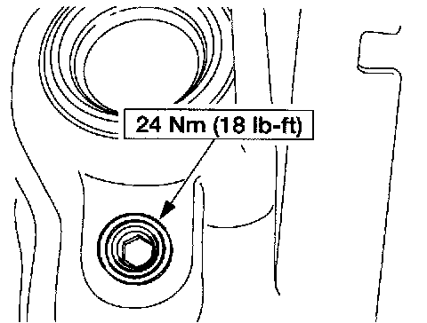
Install the cylinder block drain plugs.

64. Install the RH engine mount.

65. Install the special tool.

66. Install the special tool.

67. Install the special tool and remove the engine from the work stand.
68. Lower the engine onto wooden blocks.

69. Remove the special tool.
70. Remove the special tool.

71. Install the special tool and raise the engine.

72. Install the power steering reservoir lower mounting bracket.
5.4L - Flywheel Bolt Sequence:

73. Install the flexplate or the flywheel and bolts. Tighten the bolts in the sequence shown.
74. Install the engine.