Removal


Material:

All cylinder heads
1. Remove the engine. Service and Repair

2. Remove the bolts and the flexplate or the flywheel.
3. CAUTION: Use care when lowering the engine, to prevent damage to the oil pan.
Lower the engine onto wooden blocks.

4. Remove the special tool.

5. Remove the power steering reservoir lower mounting bracket.

6. Install the special tool.

7. Install the special tool.
8. Mount the engine on a suitable work stand.

9. Remove the special tool.

10. Remove the special tool.

11. Remove the RH engine mount.

12. NOTE: LH shown, RH similar.
Remove the cylinder block drain plugs, and drain the coolant in a suitable container.

13. Disconnect the LH radio frequency interference capacitor and cylinder head temperature (CHT) sensor electrical connectors.

14. Disconnect the camshaft position (CMP) sensor electrical connector.

15. Disconnect the RH radio frequency interference capacitor electrical connector.
16. Disconnect the knock sensor electrical connector.
17. Disconnect all necessary wiring ties or routing clips, remove the engine control sensor wiring harness from the valve cover studs and position it aside.
18. NOTE: RH shown, LH similar.

Remove the nuts, the hose support and the two radio interference capacitors.

19. Remove the crankcase ventilation tube from the LH valve cover.
20. CAUTION: Do not use metal scrapers, wire brushes, power abrasive discs or other abrasive means to clean the sealing surfaces. These tools cause scratches and gouges which make leak paths. Use a plastic scraping tool to remove all traces of old sealant.
NOTE: The bolts are part of the valve cover and should not be removed.

Remove the LH valve cover.
- Fully loosen the bolts and remove the valve cover.
- Clean the valve cover mating surface of the cylinder head with silicone gasket remover and metal surface prep. Follow the directions on the packaging.
- Inspect the valve cover gasket. If the gasket is damaged, remove and discard the gasket. Clean the valve cover gasket groove with soap and water or a suitable solvent.
21. CAUTION: Do not use metal scrapers, wire brushes, power abrasive discs or other abrasive means to clean the sealing surfaces. These tools cause scratches and gouges which make leak paths. Use a plastic scraping tool to remove all traces of old sealant.
NOTE: The bolts are part of the valve cover and should not be removed.
NOTE: Windsor engine shown; Romeo engine similar.

Remove the RH valve cover.
- Fully loosen the bolts and remove the valve cover.
- Clean the valve cover mating surface of the cylinder head with silicone gasket remover and metal surface prep. Follow the directions on the packaging.
- Inspect the valve cover gasket. If the gasket is damaged, remove and discard the gasket. Clean the valve cover gasket groove with soap and water or a suitable solvent.

22. Remove the bolt and the belt idler pulley.
23. Remove the coolant pump pulley.

1. Remove the bolts.
2. Remove the coolant pump pulley.

24. Remove and discard the crankshaft pulley bolt. Use the special tool to remove the crankshaft pulley.

25. Use the special tool to remove the crankshaft front oil seal.

26. Remove the bolts.

27. NOTE: Correct fastener location is essential for assembly procedure. Record fastener location. Remove the fasteners.

28. Remove the engine front cover from the cylinder block.

29. Remove the crankshaft sensor ring from the crankshaft.
30. CAUTION: Use care when removing the spark plugs.
NOTE: Use compressed air to remove any foreign material from the spark plug well before removing the spark plugs.
Remove the eight spark plugs.

31. Install the special tool between the valve spring coils to prevent valve stem seal damage.

32. NOTE: The camshaft roller followers must be reinstalled in their original locations. Record the camshaft roller follower locations.
NOTE: Position the cam lobe away from the camshaft roller follower prior to removing each camshaft roller follower.
Use the special tool to compress the valve springs, and remove the camshaft roller followers.

33. Remove the special tool.

34. Position the crankshaft with the keyway at the 12 o'clock position.
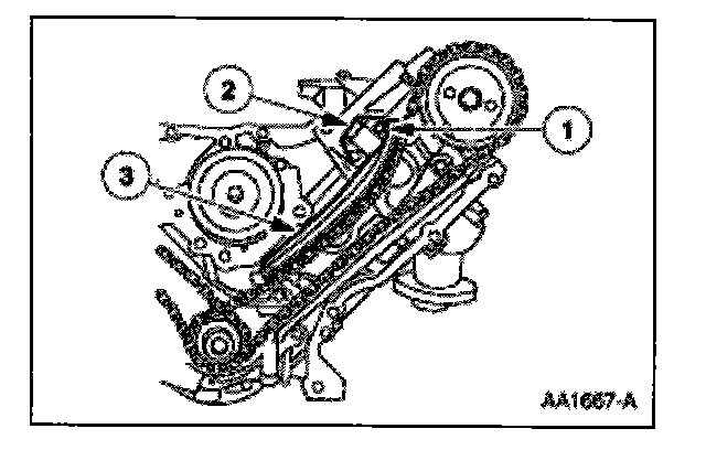
35. Remove the timing chain tensioning system from both timing chains.
1. Remove the bolts.
2. Remove the timing chain tensioners.
3. Remove the timing chain tensioner arms.

36. Remove the RH and LH timing chains and the crankshaft sprocket(s).
- Remove the RH timing chain from the camshaft sprocket.
- Remove the RH timing chain from the crankshaft sprocket.
- Remove the LH timing chain from the camshaft sprocket. Remove the LH timing chain and crankshaft sprocket(s).

37. Remove both timing chain guides.
- Remove the bolts. Remove both timing chain guides.
RH Cylinder Head

38. Remove the RH exhaust manifold.
1. Remove the nuts.
2. Remove the RH exhaust manifold.
3. Remove the RH exhaust manifold gasket.
LH Cylinder Head

39. Remove the LH exhaust manifold.
1. Remove the nuts.
2. Remove the LH exhaust manifold.
3. Remove the LH exhaust manifold gasket.

40. Remove the bolt and the oil level indicator tube.
All Cylinder Heads
41. Clean and inspect the exhaust manifolds.

42. Install the special tools on both ends of the cylinder head.
43. NOTE: The hydraulic lash adjusters must be reinstalled in their original locations. Record the hydraulic lash adjuster locations.

Remove the hydraulic lash adjusters.
RH Cylinder Head
44. CAUTION: The cylinder head must be cool before removing it from the engine. Cylinder head warpage can result if a warm or hot cylinder head is removed.
CAUTION: Place clean shop towels over exposed engine cavities. Carefully remove the towels so foreign material is not dropped into the engine.
CAUTION: The cylinder head bolts must be discarded and new bolts installed. They are tighten-to-yield designed and cannot be reused.
CAUTION: Do not use metal scrapers, wire brushes, power abrasive discs or other abrasive means to clean the sealing surfaces. These tools cause scratches and gouges that make leak paths. Use a plastic scraping tool to remove all traces of the head gasket.
CAUTION: Aluminum surfaces are soft and can be scratched easily. Never place the cylinder head gasket surface, unprotected, on a bench surface.

Remove the bolts and the RH cylinder head.
Discard the cylinder head gasket. Discard the cylinder head bolts.
LH Cylinder Head
45. CAUTION: The cylinder head must be cool before removing it from the engine. Cylinder head warpage can result if a warm or hot cylinder head is removed.
CAUTION: Place clean shop towels over exposed engine cavities. Carefully remove the towels so foreign material is not dropped into the engine.
CAUTION: The cylinder head bolts must be discarded and new bolts installed. They are tighten-to-yield designed and cannot be reused.
CAUTION: Do not use metal scrapers, wire brushes, power abrasive discs or other abrasive means to clean the sealing surfaces. These tools cause scratches and gouges that make leak paths. Use a plastic scraping tool to remove all traces of the head gasket.
CAUTION: Aluminum surfaces are soft and can be scratched easily. Never place the cylinder head gasket surface, unprotected, on a bench surface.

Remove the bolts and the LH cylinder head.
Discard the cylinder head gasket.
Discard the cylinder head bolts.
All Cylinder Heads
46. CAUTION: Do not use metal scrapers, wire brushes, power abrasive discs or other abrasive means to clean the sealing surfaces. These tools cause scratches and gouges that make leak paths. Use a plastic scraping tool to remove all traces of the head gasket.
CAUTION: Observe all warnings or cautions and follow all application directions contained on the packaging of the silicone gasket remover and the metal surface prep.
NOTE: If there is no residual gasket material present, metal surface prep can be used to clean and prepare the surfaces.
Clean the cylinder head-to-cylinder block mating surfaces of both the cylinder head and the cylinder block.
1. Remove any large deposits of silicone or gasket material with a plastic scraper.
2. Apply silicone gasket remover, following package directions, and allow to set for several minutes.
3. Remove the silicone gasket remover with a plastic scraper. A second application of silicone gasket remover may be required if residual traces of silicone or gasket material remain.
4. Apply metal surface prep, following package directions, to remove any remaining traces of oil or coolant, and to prepare the surfaces to bond with the new gasket. Do not attempt to make the metal shiny. Some staining of the metal surfaces is normal.
47. NOTE: The straightedge used must be flat within 0.0051 mm (0.0002 in) per foot of tool length.
Support the cylinder head on a bench with the head gasket side up. Inspect all areas of the deck face with a straightedge, paying particular attention to the oil pressure feed area. The cylinder head must not have depressions deeper than 0.0254 mm (0.001 in) across a 38.1 mm (1.5 in) square area, or scratches more than 0.0254 mm (0.001 in).