Part 1
Engine - 5.4L
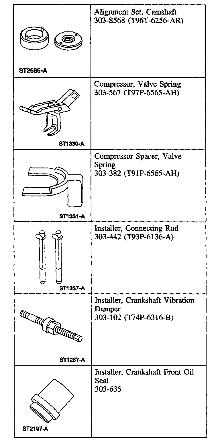
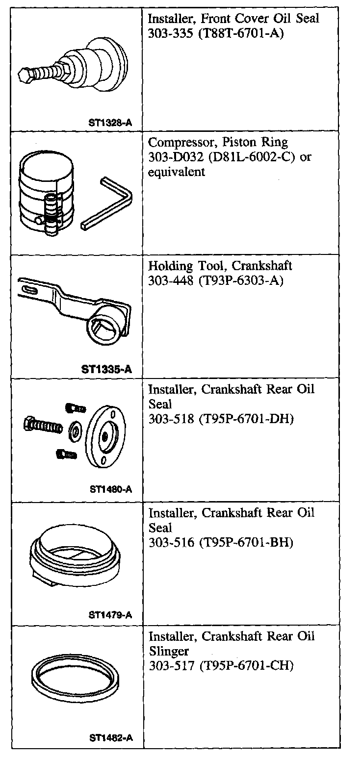
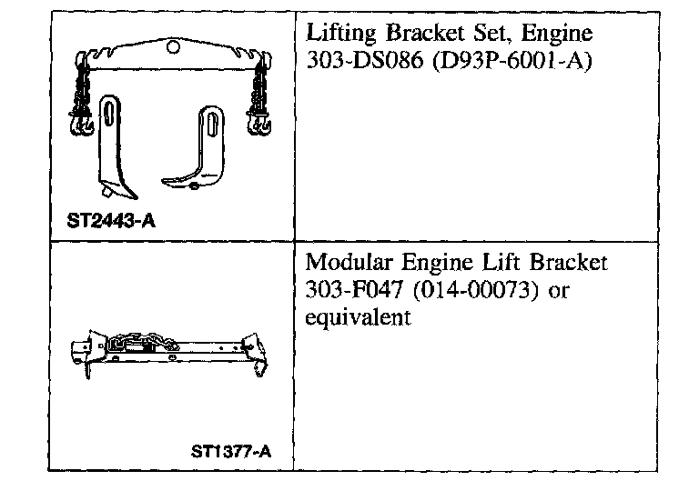
Special Tool(s)
Part 1 Of 3:
Part 2 Of 3:
Part 3 Of 3:
Assembly
All engines

1. Record the main bearing code found on the front of the engine block.

2. Record the main bearing code found on the back of the crankshaft.
Bearing Select Fit Chart, Standard Bearings
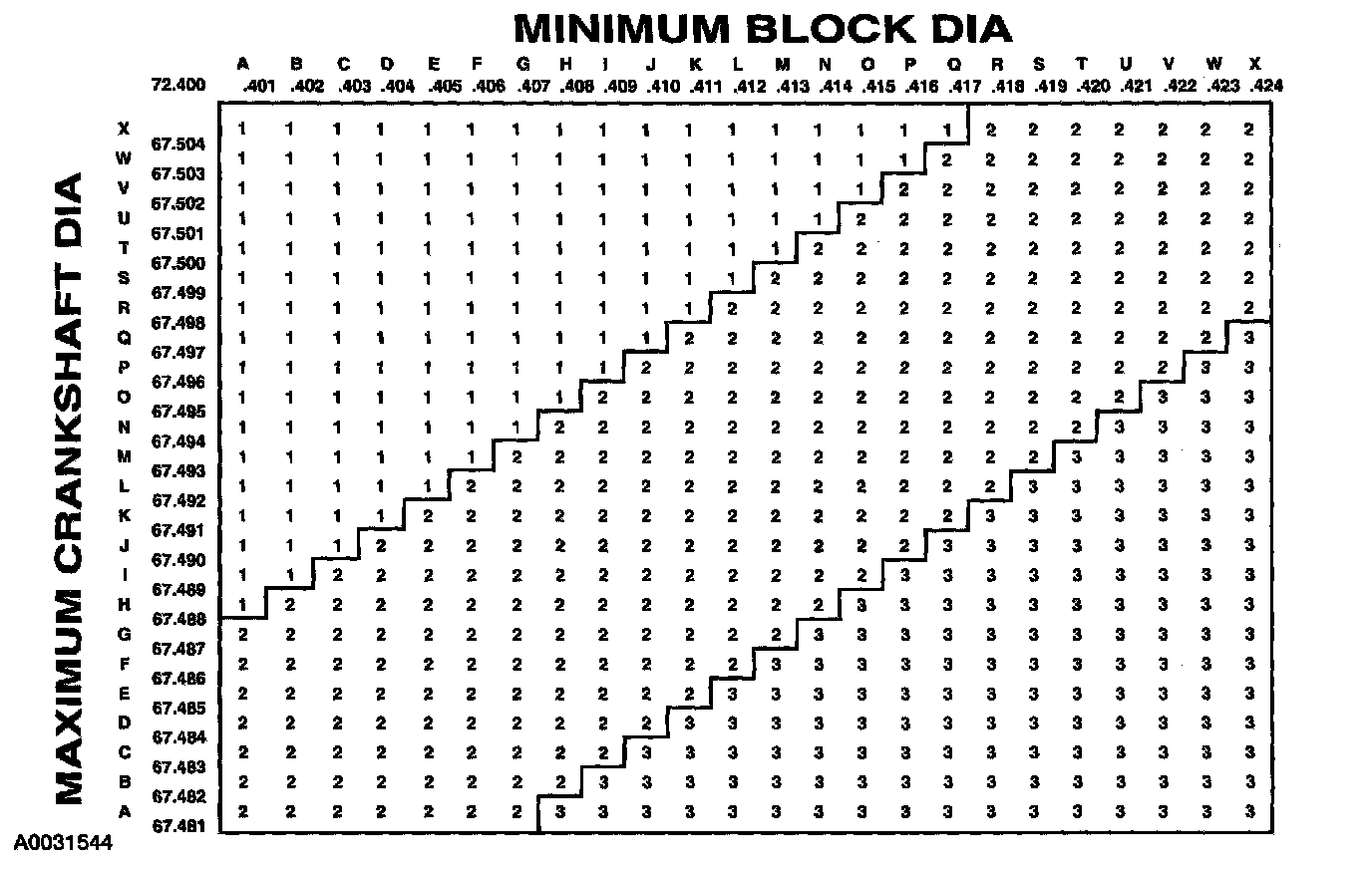
3. Using the data recorded earlier and the Bearing Select Fit Chart, Standard Bearings, determine the required bearing grade for each main bearing.
- Read the first letter of the engine block main bearing code and the first letter of the crankshaft main bearing code.
- Read down the column below the engine block main bearing code letter, and across the row next to the crankshaft main bearing code letter, until the two intersect. This is the required bearing grade for the number one crankshaft main bearing.
- As an example, if the engine block code letter is "F" and the crankshaft code letter is "D", the correct bearing grade for this main bearing is a "2".
- Repeat this process for the remaining four main bearings.
Bearing Select Fit Chart, Oversize Bearings
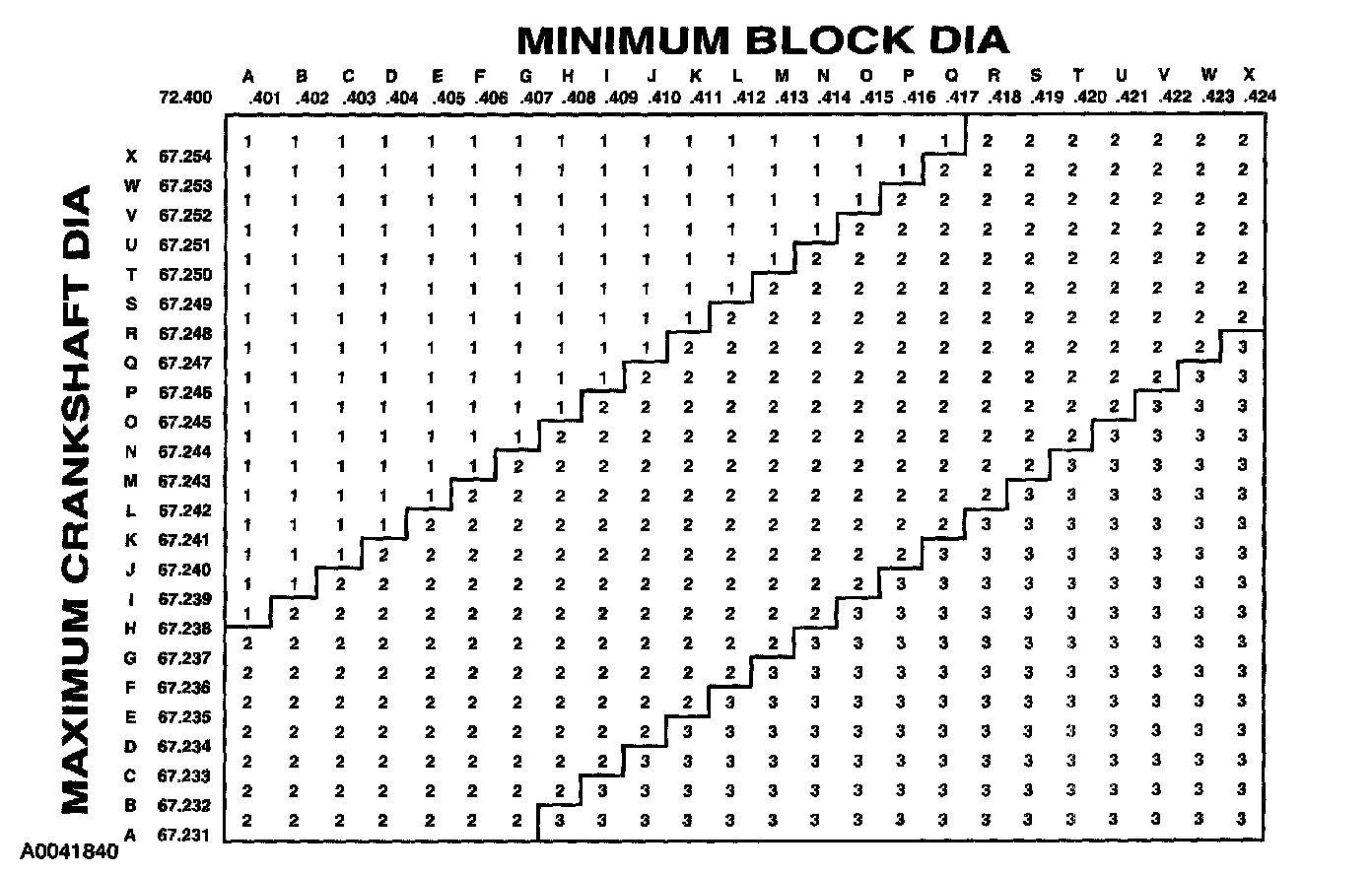
4. If oversize bearings are being used, use the procedure in the previous step and the Bearing Select Fit Chart, Oversize Bearings to determine the required bearing grade for each main bearing.
5. NOTE: Before assembling the cylinder block, all sealing surfaces must be free of chips, dirt, paint and foreign material. Also, make sure the coolant and oil passages are clear.
Install the crankshaft upper main bearings into the cylinder block and lubricate them with clean engine oil.

6. NOTE: The upper thrust washers are shown for location purposes only. Do not install the upper thrust washers until the crankshaft is installed. Refer to the following two steps.
Install the crankshaft onto the upper crankshaft main bearings.

7. NOTE: The oil groove on the thrust washer must face toward the front of the engine (against the crankshaft thrust surface).
Push the crankshaft rearward and install the rear crankshaft upper thrust washer at the back of the No. 5 main boss.

8. NOTE: The oil groove on the thrust washer must face toward the front of the engine (against the crankshaft surface).
Push the crankshaft forward and install the front crankshaft upper thrust washer at the front of the No. 5 main boss.

9. NOTE: To aid in assembly, apply petroleum jelly to the back of the crankshaft thrust washer.
NOTE: The oil groove on the thrust washer must face toward the rear of the engine (crankshaft surface).
Install the lower crankshaft thrust washer to the back side of the No. main bearing cap, with oil grooves facing the crankshaft surface.

10. Install the crankshaft lower main bearings into the main bearing caps and lubricate them with clean engine oil. Locate the main bearing cap on the cylinder block and tap into place using a plastic or dead-blow hammer.
11. Install the dowel pins so the flat sides face the crankshaft.

12. Install the vertical main bearing cap fasteners and tighten in the sequence shown.
- Tighten to 40 Nm (30 ft. lbs.).
- Tighten an additional 90°.
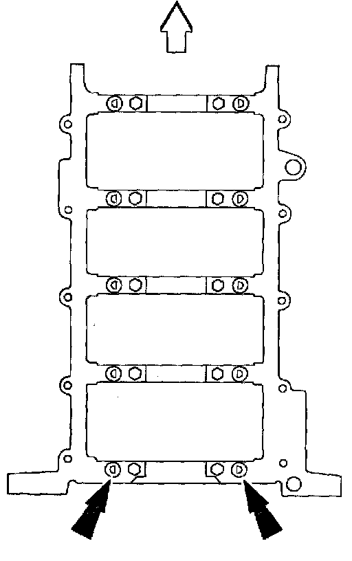
5.4L - Side Bolt Sequence:

13. Install the side bolts and tighten them in the sequence shown.
- Tighten to 30 Nm (22 ft. lbs.).
- Tighten an additional 90°.

14. CAUTION: Do not scratch the cylinder walls or crankshaft journals with the connecting rod.
NOTE: The next three steps are for all eight connecting rods, rod caps and pistons. Only one connecting rod, rod cap and piston is shown.
NOTE: Make sure the identification marks on the piston and connecting rod face toward the front of the engine.
Use the special tools to install the piston and connecting rod with the upper connecting rod bearing in place.

15. CAUTION: Do not scratch the cylinder walls or crankshaft journals with the connecting rod.
Once the connecting rod is seated on the crankshaft journal, remove the Connecting Rod Installer.
16. CAUTION: The rod cap installation must keep the same orientation as marked during disassembly.
NOTE: The connecting rod caps are of the "cracked" design and must mate with the connecting rod ends. Excessive bearing clearance will result if not mated correctly.
Position the lower bearing and connecting rod, and install the new bolts loosely.

17. NOTE: Main bearing caps are removed for clarity.
Tighten the bolts in two stages, using the sequence shown.
- Stage 1: Tighten to 43 Nm (32 ft. lbs.).
- Stage 2: Tighten an additional 105°.

18. Position the oil pump and install the bolts loosely. Tighten the bolts in the sequence shown.
19. CAUTION: The gasket sealing surfaces on the cylinder head and cylinder block must be clean.
CAUTION: The use of sealing aids (aviation cement, copper spray and glue) is not permitted. The gasket must be installed dry.
CAUTION: The new gasket has a film coating which is crucial to the gasket's ability to seal correctly. Do not scratch the gasket.
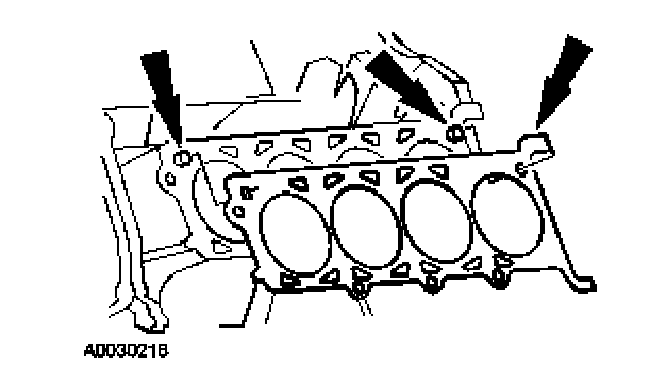
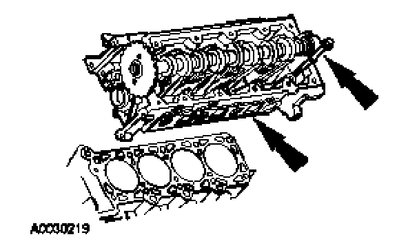
NOTE: RH head gasket shown, LH head gasket similar.
Install the head gasket over the dowel pins.
20. CAUTION: Cylinder head machining or milling is not authorized by the Ford Motor Company. Cylinder head flatness must be within 0.0254 mm (0.001 in) across a 38.1 mm (1.5 in) square area.
CAUTION: The gasket sealing surfaces on the cylinder head and cylinder block must be clean.
CAUTION: The use of sealing aids (aviation cement, copper spray and glue) is not permitted. The gasket must be installed dry.
CAUTION: Do not allow the dowels to scratch the sealing surface of the cylinder head during cylinder head installation.
NOTE: The new cylinder head bolts must be lightly oiled with a rag, and allowed to drain for a few minutes prior to installation.
NOTE: RH cylinder head shown, LH cylinder head similar.
Install the cylinder head on the dowels and the head gasket. Loosely install new bolts.
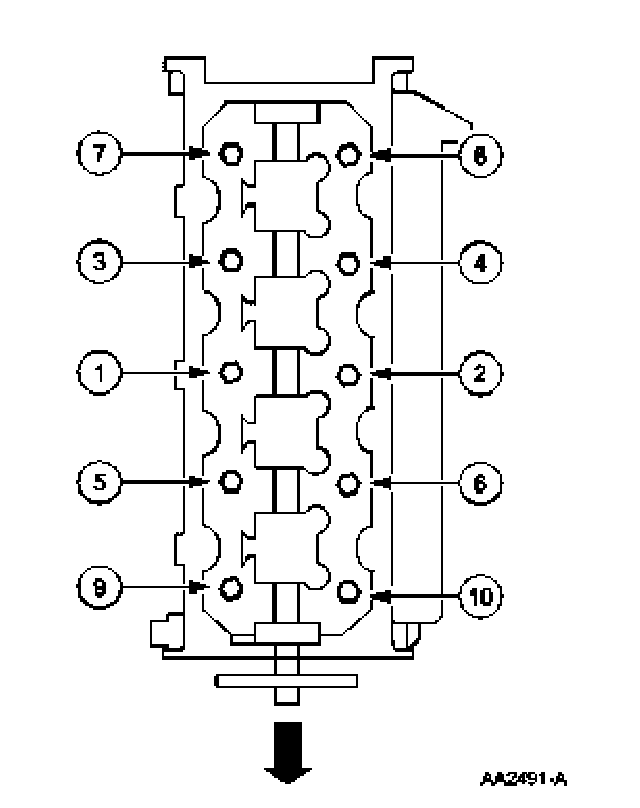
LH cylinder head
21. NOTE: Make sure to tighten the bolts in sequence in the following three stages.
Tighten the LH bolts in the sequence shown.
- Stage 1: Tighten to 40 Nm (30 ft. lbs.).
- Stage 2: Tighten an additional 90°.
- Stage 3: Tighten an additional 90°.
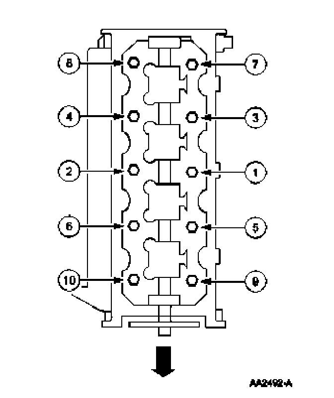
RH cylinder head
22. NOTE: Make sure to tighten the bolts in sequence in the following three stages.
Tighten the RH bolts in the sequence shown.
- Stage 1: Tighten to 40 Nm (30 lb-ft).
- Stage 2: Tighten an additional 90 degrees.
- Stage 3: Tighten an additional 90 degrees degrees
All cylinder heads
23. Remove the special tools on both ends of the cylinder head
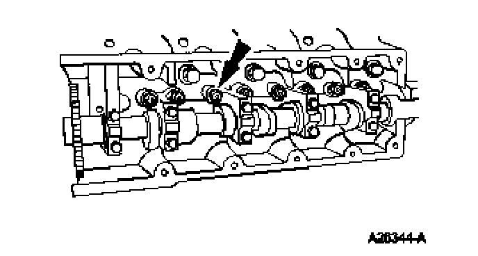
24. NOTE: Lubricate the hydraulic lash adjusters with clean engine oil.
Install the hydraulic lash adjusters in their original locations
RH cylinder head
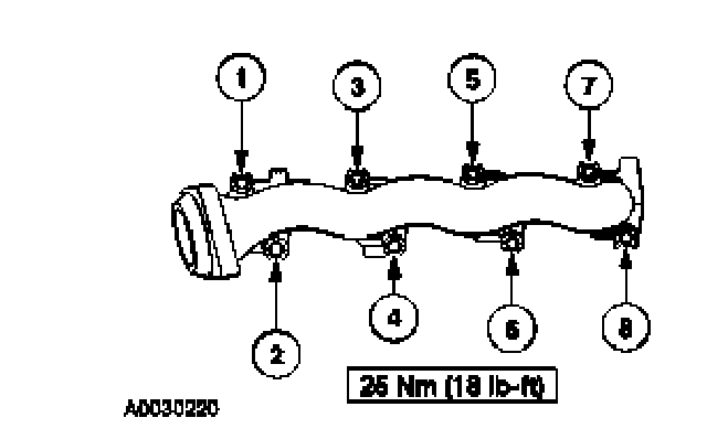
25. Install the RH exhaust manifold gaskets and the exhaust manifold. Tighten the nuts in the sequence shown.
LH cylinder head
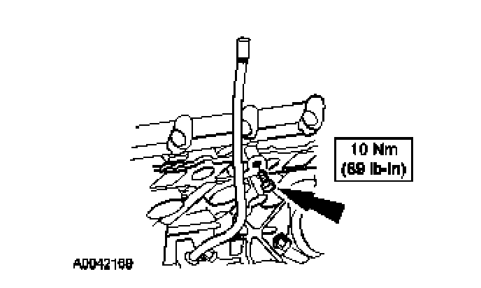
26. NOTE: Lubricate the O-ring seal with clean engine oil.
Install the oil level indicator tube.
Install a new O-ring seal on the oil level indicator tube.
Install the oil level indicator tube.
Install the bolt.
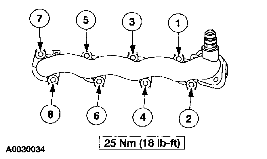
27. Install the LH exhaust manifold and the exhaust manifold gaskets. Tighten the nuts in the sequence shown.
28. CAUTION: Timing chain procedures must be followed exactly or damage to valves and pistons will result.
Compress the tensioner plunger, using a vise.

29. Install a retaining clip on the tensioner to hold the plunger in during installation.

30. Remove the tensioner from the vise.
31. If the copper links are not visible, mark two links on one end and one link on the other end, and use as timing marks.

32. Install the timing chain guides.

33. Pre-position the camshafts.
1 Rotate the LH camshaft with the Camshaft Positioning Tool until the timing mark is approximately at 12 o'clock.
2 Rotate the RH camshaft with the Camshaft Positioning Tool until the timing mark is approximately at 11 o'clock.

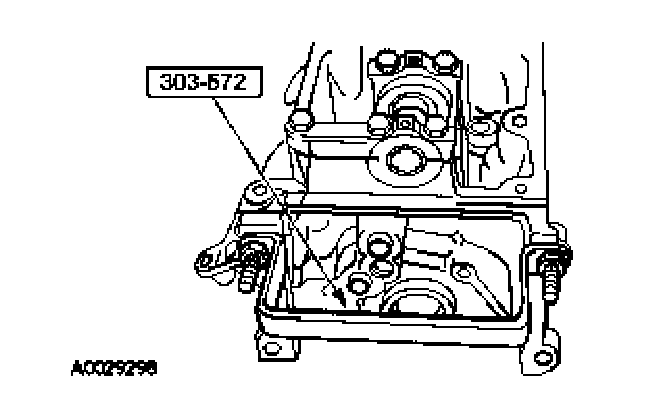
34. CAUTION: Rotate the crankshaft counterclockwise only. Do not rotate past position shown or severe piston and valve damage can occur.
NOTE: The number one piston is at Top Dead Center (TDC) when the stud on the engine block fits into the slot in the handle of the special tool.
Position the crankshaft so the number one cylinder is at TDC with the special tool.

35. Remove the Crankshaft Holding Tool.
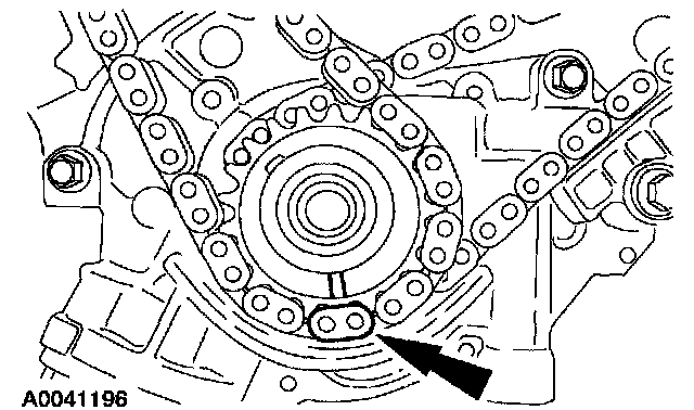
36. Install the crankshaft sprocket, making sure the flange faces forward.

37. Position the lower end of the LH (inner) timing chain on the crankshaft sprocket, aligning the timing mark on the outer flange of the crankshaft sprocket with the single copper (marked) link on the chain.

38. NOTE: Make sure the upper half of the timing chain is below the tensioner arm dowel.
NOTE: If necessary, use the Camshaft Alignment Set to adjust the camshaft sprocket slightly to obtain timing mark alignment.
Position the timing chain on the camshaft sprocket with the camshaft sprocket timing mark positioned between the two copper (marked) chain links.

39. NOTE: The LH timing chain tensioner arm has a bump near the dowel hole for identification.
Position the LH timing chain tensioner arm on the dowel pin and install the LH timing chain tensioner.

40. Remove the retaining clip from the LH timing chain tensioner.

41. Position the lower end of the RH (outer) timing chain on the crankshaft sprocket, aligning the timing mark on the sprocket with the single copper (marked) chain link.
42. NOTE: The lower half of the timing chain must be positioned above the tensioner arm dowel.
NOTE: If necessary, use the Camshaft Alignment Set to adjust the camshaft sprocket slightly to obtain timing mark alignment.
Position the RH timing chain on the camshaft sprocket. Make sure the camshaft sprocket timing mark is positioned between the two copper (marked) chain links.

43. Position the RH timing chain tensioner arm on the dowel pin and install the RH timing chain tensioner.

44. Remove the retaining clip from the RH timing chain tensioner.