On Board Diagnostics Monitors
OBD-I and OBD-II Overview
The California Air Resources Board (CARB) began regulating On Board Diagnostic (OBD) Systems for vehicles sold in California beginning with the 1988 model year. The initial requirements, known as OBD-I, required identifying the likely area of malfunction with regard to the fuel metering system, Exhaust Gas Recirculation (EGR) system, emission-related components and the Powertrain Control Module (PCM). A Malfunction Indicator Lamp (MIL) labeled CHECK ENGINE or SERVICE ENGINE SOON was required to illuminate and alert the driver of the malfunction and the need to service the emission control system. A fault code or Diagnostic Trouble Code (DTC) was required to assist in identifying the system or component associated with the fault.
Starting with the 1994 model year, both CARB and Environmental Protection Agency (EPA) mandated enhanced OBD systems, commonly known as OBD-II. The objectives of the OBD-II system are to improve air quality by reducing high in-use emissions caused by emission-related malfunctions, reducing the time between the occurrence of a malfunction and its detection and repair, and assisting in the diagnosis and repair of emission-related problems.
OBD-II/Federal OBD requirements apply to:
^ Gasoline engines: All California and Federal passenger cars, California trucks up to 14,000 lb. GVWR (Gross Vehicle Weight Rating) and Federal trucks up to 8,500 lbs. GVWR. Federal heavy-duty trucks up to 10,000 lb. GVWR choosing to certify using Light Duty Truck provisions must comply with OBD-II requirements. Federal heavy-duty trucks over 8,500 lbs. GVWR are not required to comply with any OBD regulation, however in order to meet minimum serviceability requirements, must comply with OBD-I requirements.
^ Diesel Engines: Diesel cars and trucks up to 8,500 lbs. GVWR and diesel engine vehicles up to 14,000 lbs. GVWR sold in California.
^ Alternative fuel vehicles (AFV): Ethanol/methanol AFVs must meet full OBD-II requirements during operation on all fuels. Bi-fuel NGVs/LPGs are required to meet OBD-II requirements while operating on gasoline. Dedicated NGVs and bi-fuel NGVs/LPGs are required to partially meet OBD-II requirements while operating on gaseous fuels.
Passenger cars and trucks sold in Canada and Mexico have Federal calibrations, unless unique calibrations are certified for Mexico at high altitude. Green states are states that choose to adopt California emission regulations. Green States receive California-certified vehicles for passenger cars and light trucks up to 6,000 lbs. GVWR.
The OBD-II system monitors virtually all emission control systems and components that can affect tailpipe or evaporative emissions. In most cases, malfunctions must be detected before emissions exceed 1.5 times the applicable 100K (passenger cars) or 120K (trucks) - mile emission standards. If a system or component exceeds emission thresholds or fails to operate within a manufacturer's specifications, a DTC will be stored and the MIL will be illuminated within two driving cycles.
The OBD-II system monitors for malfunctions either continuously, regardless of driving mode, or non-continuously, once per drive cycle during specific drive modes. A pending DTC is stored in the PCM Keep Alive Memory (KAM) when a malfunction is initially detected. This pending DTC may be erased on the third vehicle restart after two consecutive drives cycles with no malfunction. However if the malfunction is still present after two consecutive drive cycles, the MIL is illuminated. Once the MIL is illuminated, three consecutive drive cycles without a malfunction detected are required to extinguish the MIL. The DTC is erased after 40 engine warm-up cycles once the MIL is extinguished.
In addition to specifying and standardizing much of the diagnostics and MIL operation, OBD-II requires the use of a standard Diagnostic Link Connector (DLC), standard communication links and messages, standardized DTCs and terminology. Examples of standard diagnostic information are freeze frame data and Inspection Maintenance (IM) Readiness Indicators.
Freeze frame data describes data stored in KAM at the point the malfunction is initially detected. Freeze frame data consists of parameters such as engine rpm and load, state of fuel control, spark, and warm-up status. Freeze frame data is stored at the time the first malfunction is detected, however, previously stored conditions will be replaced if a fuel or misfire fault is detected. This data is accessible with the scan tool to assist in repairing the vehicle.
OBD Inspection Maintenance (IM) Readiness indicators show whether all of the OBD monitors have been completed since the last time KAM or the PCM DTC(s) have been cleared. Ford also stores a P1000 DTC to indicate that some monitors have not completed. In some states, it may be necessary to perform an OBD check in order to renew a vehicle registration. The IM Readiness indicators must show that all monitors have been completed prior to the OBD check.


Vehicles not required to comply with OBD-II requirements will utilizes an OBD-I system. OBD-I systems are used on all over 8,500 lbs. GVWR Federal truck calibrations. OBD-I vehicles use the same data communication link, data link connector (DLC) and PCM software as the corresponding OBD-II vehicle. Differences between OBD-I and OBD-II vehicles may be removal of the rear oxygen sensor(s), fuel tank pressure sensor, canister vent solenoid and PCM calibration. The table lists what monitors and functions have been altered for the OBD-I calibration.
The following section provides a general description of each On Board Diagnostic monitor. In these descriptions, the monitor strategy, hardware, testing requirements and methods are presented to provide an overall understanding of monitor operation. An illustration of each monitor is also provided. These illustrations should be used as typical examples and are not intended to represent all possible vehicle configurations.
Each illustration depicts the PCM as the main focus with primary inputs and outputs for each monitor. The icons to the left of the PCM represent the inputs used by each of the monitor strategies to enable or activate the monitor. The components and subsystems to the right of the PCM represent the hardware and signals used while performing the tests and the systems being tested. The Comprehensive Component Monitor (CCM) illustration has numerous components and signals involved and are shown generically. When referring to the illustrations, match the numbers to the corresponding numbers in the monitor descriptions for a better comprehension of the monitor and associated DTC's.
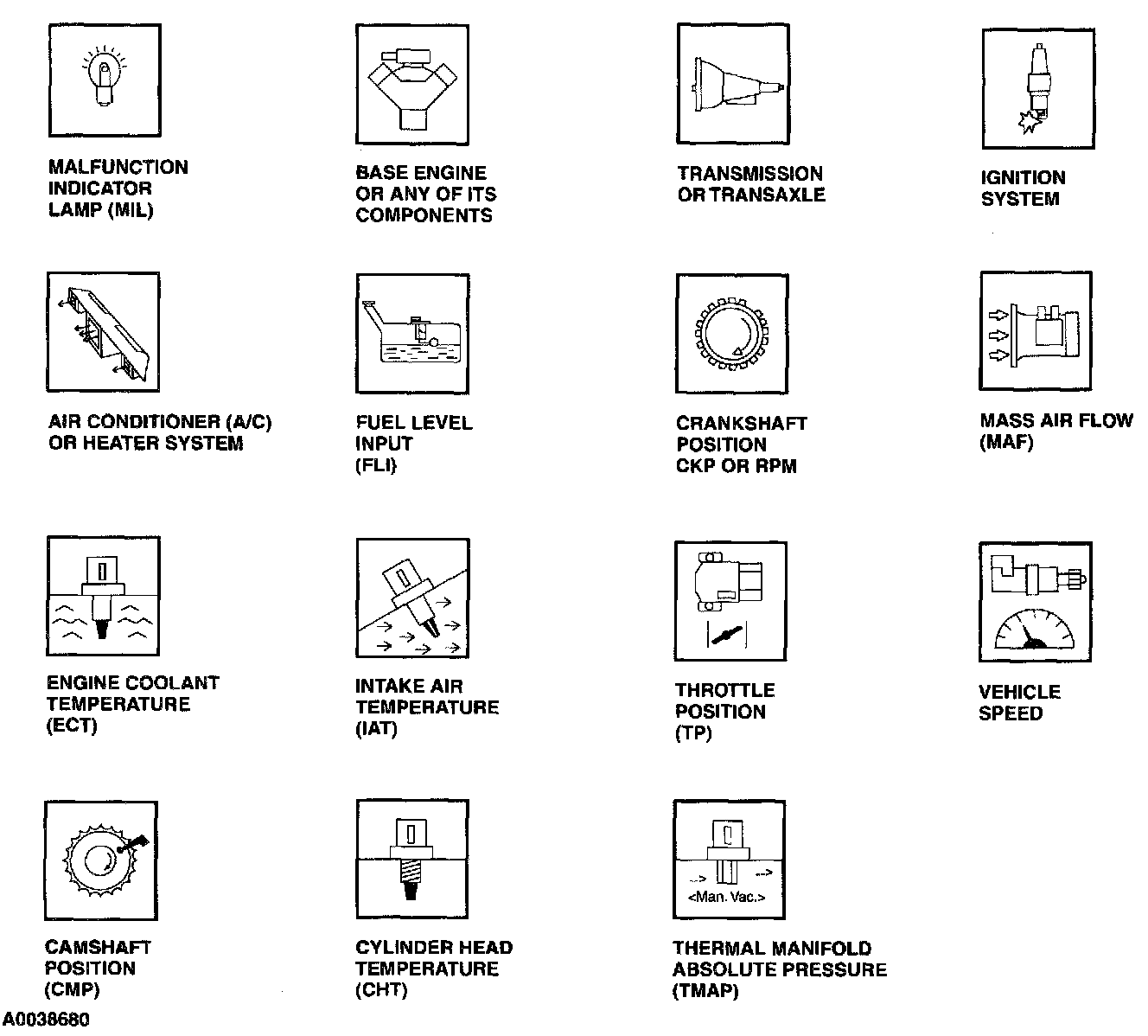
These icons are used in the illustrations of the On Board Diagnostic monitors.