Deactivate
SUPPLEMENTAL RESTRAINT SYSTEM (SRS) DEACTIVATION AND REACTIVATIONSpecial Tool(s):
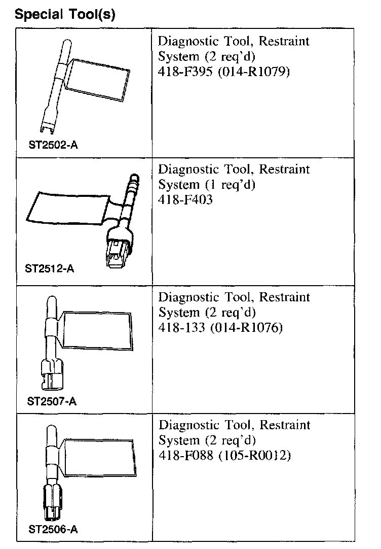
SPECIAL TOOL(S)
Deactivation
WARNING:
- Always wear safety glasses when repairing an air bag supplemental restraint system (SRS) vehicle and when handling an air bag module. This will reduce the risk of injury in the event of an accidental deployment.
- Carry a live air bag module with the air bag and trim cover pointed away from your body. This will reduce the risk of injury in the event of an accidental deployment.
- Do not set a live air bag module down with the trim cover face down. This will reduce the risk of injury in the event of an accidental deployment.
- After deployment, the air bag surface can contain deposits of sodium hydroxide, a product of the gas generant combustion that is irritating to the skin. Wash your hands with soap and water afterwards.
- Never probe the connectors on the air bag module. Doing so can result in air bag deployment, which can result in personal injury.
- The safety belt pretensioner is a pyrotechnic device. Always wear safety glasses when repairing an airbag equipped vehicle and when handling a safety belt buckle pretensioner or safety belt retractor pretensioner. Never probe a pretensioner electrical connector. Doing so could result in pretensioner or air bag deployment and could result in personal injury.
- Never probe the connectors on the safety canopy module. Doing so can result in safety canopy module deployment.
- Vehicle sensor orientation is critical for proper system operation. If a vehicle equipped with an air bag supplemental restraint system (SRS) is involved in a collision, inspect the sensor mounting bracket and wiring pigtail for deformation. Replace and properly position the sensor or any other damaged supplemental restraint system (SRS) components whether or not the air bag is deployed.
- Restraint system diagnostic tools are for service only. Tools must be removed prior to operating the vehicle over the road. Failure to remove restraint system diagnostic tools could result in injury and possible violation of vehicle safety standards.
NOTE:
- If a seat equipped with a seat mounted side air bag and/or a safety belt pretensioner (if equipped) system is being serviced the air bag system must be deactivated.
- Restraint system diagnostic tools MUST be installed under the seats in the seat side air bag (if equipped) and safety belt pretensioner (if equipped) to floor connectors.
- Diagnostics or repairs are not to be carried out on a seat equipped with a seat side air bag with the seat in the vehicle. Prior to attempting to diagnose or repair a seat concern when equipped with a seat side air bag, the seat must be removed from the vehicle and the restraint system diagnostic tools must be installed in the seat side air bag electrical connectors. The restraint system diagnostic tools must be removed prior to operating the vehicle over the road.
- After diagnosing or repairing an SRS, the restraint system diagnostic tools must be removed before operating the vehicle over the road.
- After diagnosing or repairing a seat system, the restraint system diagnostic tools must be removed before operating the vehicle over the road.
- The SRS must be fully operational and free of faults before releasing the vehicle to the customer.
All vehicles
1. WARNING: To avoid accidental deployment and possible personal injury, the backup power supply must be depleted before repairing or replacing any front or side air bag supplemental restraint system (SRS) components and before servicing, replacing, adjusting or striking components near the front or side air bag sensors, such as doors, instrument panel, console, door latches, strikers, seats and hood latches.
The front impact severity sensor is located at the bottom of the hood latch support bracket.
The first row side impact sensors (if equipped) are located in the first row doors, behind the door trim panel.
The second row side impact sensors (if equipped) are located at or near the base of the C-pillars.
To deplete the backup power supply energy, disconnect the battery ground cable and wait at least one minute. Be sure to disconnect auxiliary batteries and power supplies (if equipped).
Disconnect the battery ground cable and wait at least one minute.
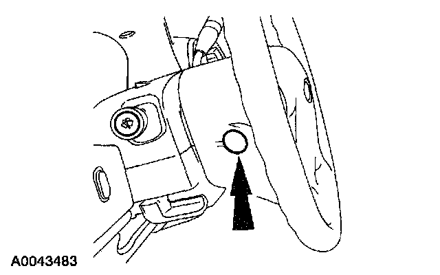
2. Remove the two steering wheel back cover plugs (one shown).

3. Remove the two driver air bag module bolts (one shown).
Expedition vehicles

4. Remove the driver air bag module.
1 Release the two retaining tabs. Disconnect the driver air bag module electrical connector.
- Label the driver air bag module squib number on the driver air bag module electrical connector before disconnecting.
2 Release the two retaining tabs. Disconnect the driver air bag module electrical connector.
- Label the driver air bag module squib number on the driver air bag module electrical connector before disconnecting.
3 Disconnect the horn switch electrical connector.
4 Remove the driver air bag module.
Navigator vehicles

5. Disconnect the driver air bag module
- Release the two tabs on each driver air bag module electrical connector and disconnect them.
- Label each driver air bag module electrical connector before disconnecting.

6. Release the tab and disconnect the driver air bag module accessories electrical connector at the top of the clockspring and remove the driver air bag module.
All vehicles

7. Attach the restraint system diagnostic tools to the clockspring electrical connectors at the top of the steering column.

8. While pushing in on the two glove compartment door tabs, position the glove compartment downward.

9. NOTE: The Expedition is shown, the Navigator is similar.
Through the glove compartment opening, release the tab and disconnect the passenger air bag module electrical connector.
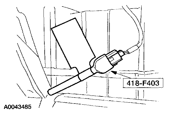
10. Attach the restraint system diagnostic tool to the vehicle harness side of the passenger air bag module electrical connector.
Vehicles without safety canopies
11. CAUTION: Do not deactivate the safety canopy module circuit by removing the safety canopy bridge resistor from the safety canopy electrical connector.
If the safety canopy bridge resistor is removed an open circuit fault will be generated by the restraints control module (RCM).
If a restraint system diagnostic tool is installed at the safety canopy electrical connector, a low resistance fault will be generated by the RCM.
Vehicles with safety canopies

12. NOTE: Inspect the shoulder safety belt guide cover for damage. If the shoulder safety belt guide cover is damaged or if it does not remain closed, install a new shoulder safety belt guide cover.
Remove the second row passenger side safety belt guide.
1 Release the retaining tab at each side and open the safety belt guide cover.
2 Remove the nut.
3 Remove the second row passenger side safety belt guide.

13. Remove the passenger side C-pillar trim panel.
1 Separate the weather-stripping along the passenger side C-pillar trim panel.
2 Remove the bolt cover and bolt.
3 Pull out to release the retainers and remove the passenger side C-pillar trim panel.

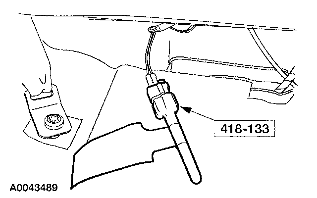
14. Disconnect the passenger side safety canopy electrical connector.
15. Attach the restraint system diagnostic tool to the vehicle harness side of the passenger side safety canopy electrical connector.
All vehicles

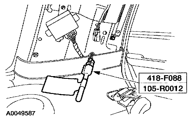
16. Disconnect the passenger seat safety belt buckle pretensioner electrical connector.
1 Slide and disengage the passenger seat safety belt buckle pretensioner electrical connector locking clip.
2 Push in to release the tab and disconnect the passenger seat safety belt buckle pretensioner electrical connector.
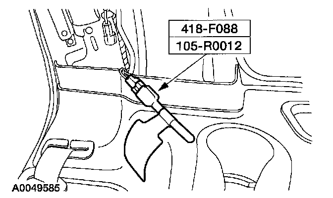
17. Attach the restraint system diagnostic tool to the passenger seat safety belt buckle pretensioner floor electrical connector.
Vehicles with safety canopies
18. NOTE: Inspect the shoulder safety belt guide cover for damage. If the shoulder safety belt guide cover is damaged or if it does not remain closed, install a new shoulder safety belt guide cover.
Remove the second row driver side safety belt guide.
1 Release the retaining tab at each side and open the safety belt guide cover.
2 Remove the nut.
3 Remove the second row driver side safety belt guide.
19. Remove the driver side C-pillar trim panel.
1 Separate the weather-stripping along the driver side C-pillar trim panel.
2 Remove the bolt cover and bolt.
3 Pull out to release the retainers and remove the driver side C-pillar trim panel.

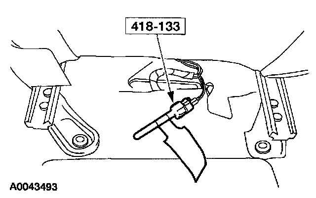
20. Disconnect the driver side safety canopy electrical connector.
21. Attach the restraint system diagnostic tool to the vehicle harness side of the driver side safety canopy electrical connector.
All vehicles

22. Disconnect the driver seat safety belt buckle pretensioner electrical connector.
1 Slide and disengage the driver seat safety belt buckle pretensioner electrical connector locking clip.
2 Push in to release the tab and disconnect the driver seat safety belt buckle pretensioner electrical connector.
23. Attach the restraint system diagnostic tool to the driver seat safety belt buckle pretensioner floor electrical connector.
24. Connect the battery ground cable.
25. With the restraint system diagnostic tools installed at all deployable devices, prove out the supplemental restraint system (SRS). Prove Out Procedure
26. Disconnect the battery ground cable and wait at least one minute.