Reactivate
SUPPLEMENTAL RESTRAINT SYSTEM (SRS) DEACTIVATION AND REACTIVATIONSpecial Tool(s):
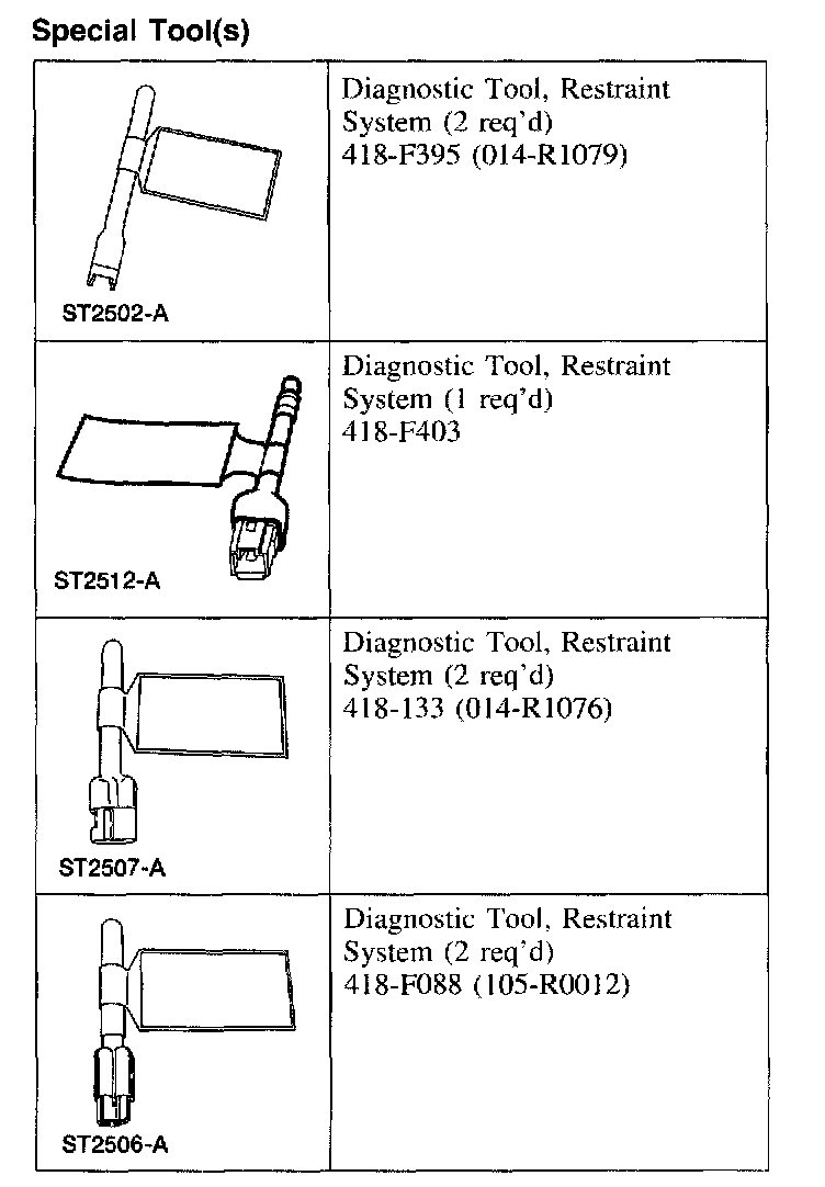
SPECIAL TOOL(S)
Reactivation
WARNING: To reduce the risk of serious personal injury, read and follow all warnings, cautions, and notes at the beginning of the deactivation procedure.
All vehicles
1. NOTE: Make sure the battery negative cable is still disconnected before proceeding with the reactivation portion of this procedure.
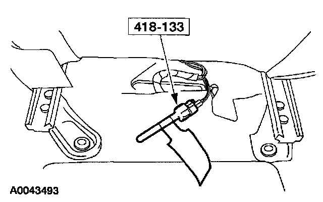
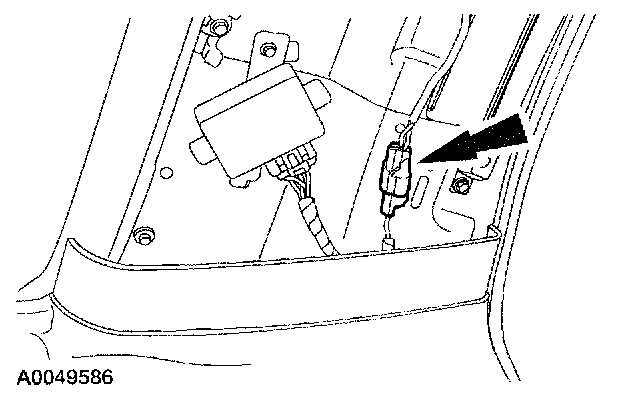
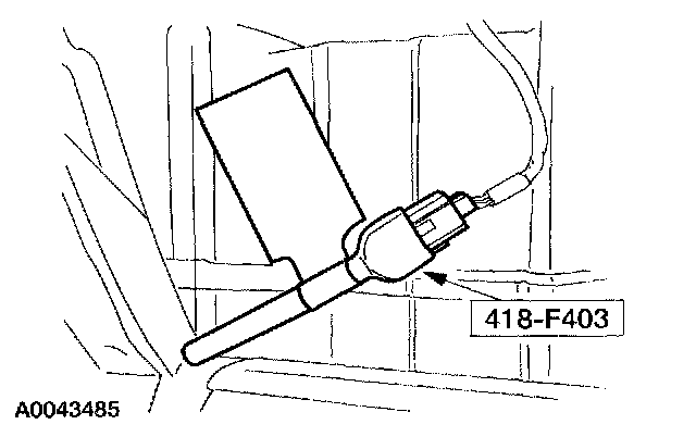
Remove the restraint system diagnostic tool from the driver seat safety belt buckle pretensioner floor electrical connector.
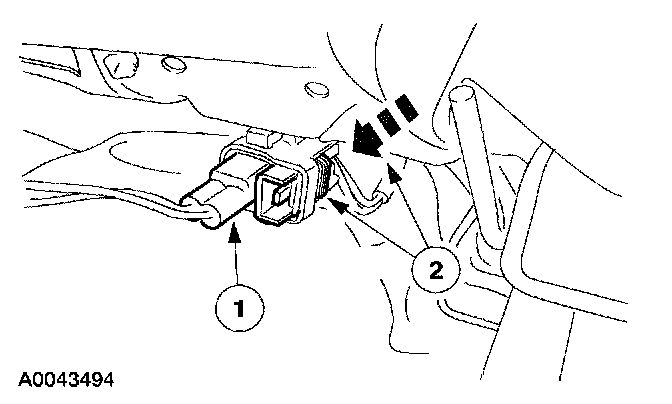
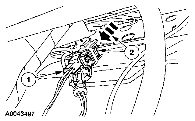
2. Connect the driver seat safety belt buckle pretensioner electrical connector.
1 Connect the driver seat safety belt buckle pretensioner electrical connector.
2 Slide and engage the driver seat safety belt buckle pretensioner electrical connector locking clip.
Vehicles with safety canopies
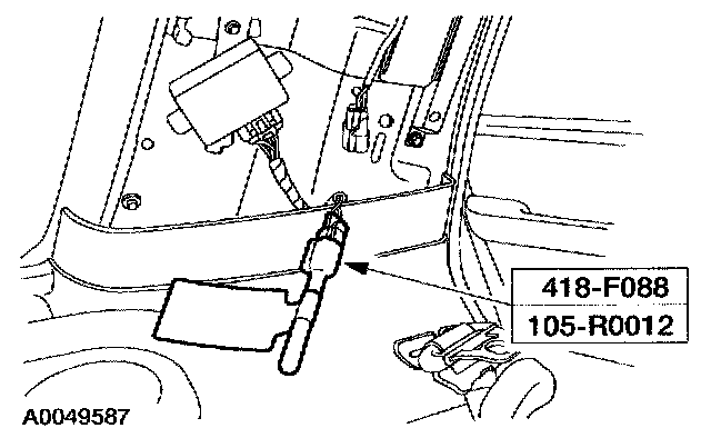
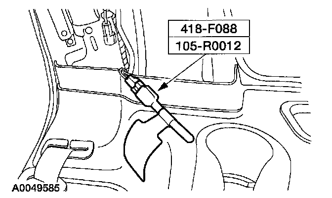
3. Remove the restraint system diagnostic tool from the vehicle harness side of the driver side safety canopy electrical connector.
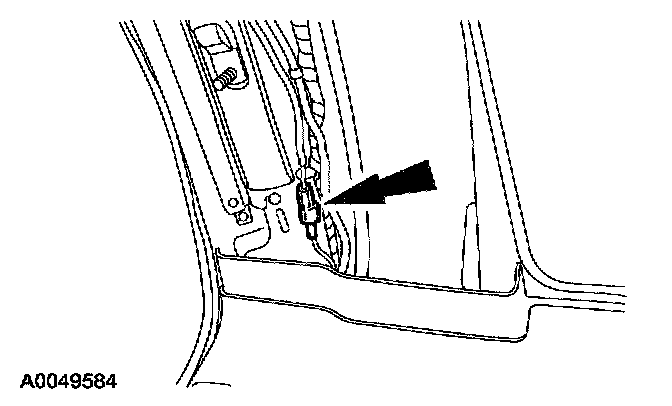
4. Connect the driver side safety canopy electrical connector.
5. WARNING: Anytime the safety canopy module has deployed, the headliner, and all A,B, and C pillar upper trim panels and attaching hardware must he replaced along with any other damaged components and hardware. Failure to do so may result in personal injury in the event of a safety canopy module deployment.
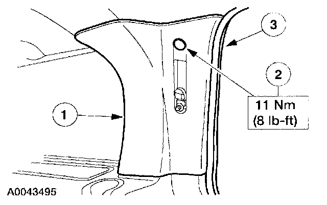
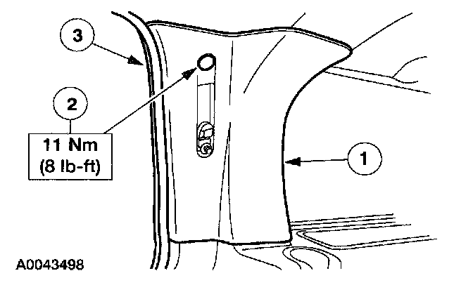
Install the driver side C-pillar trim panel.
1 Position the driver side C-pillar trim panel and push in, engaging the retainers.
2 Install the bolt and bolt cover.
3 Install the weather-stripping along the driver side C-pillar trim panel.
6. NOTE:
- Inspect the shoulder safety belt guide cover for damage. If the shoulder safety belt guide cover is damaged or if it does not remain closed, install a new shoulder safety belt guide cover.
- Make sure the safety belt is not twisted prior to installation.
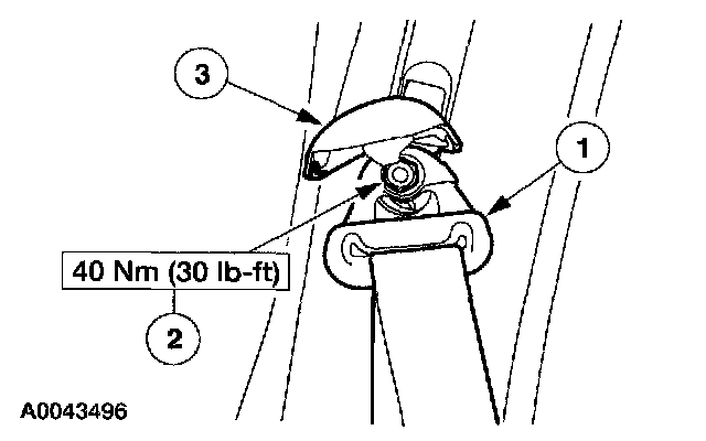
Install the second row driver side safety belt guide.
1 Position the second row driver side safety belt guide.
2 Install the nut.
3 Close the safety belt guide cover.
All vehicles
7. Remove the restraint system diagnostic tool from the passenger seat safety belt buckle pretensioner floor electrical connector.
8. Connect the passenger seat safety belt buckle pretensioner electrical connector.
1 Connect the passenger seat safety belt buckle pretensioner electrical connector.
2 Slide and engage the passenger seat safety belt buckle pretensioner electrical connector locking clip.
Vehicles with safety canopies
9. Remove the restraint system diagnostic tool from the vehicle harness side of the passenger side safety canopy electrical connector.
10. Connect the passenger side safety canopy electrical connector.
11. WARNING: Anytime the safety canopy module has deployed, the headliner, and all A, B, and C pillar upper trim panels and attaching hardware must be replaced along with any other damaged components and hardware. Failure to do so may result in personal injury in the event of a safety canopy module deployment.
Install the passenger C-pillar trim panel.
1 Position the passenger side C-pillar trim panel and push in, engaging the retainers.
2 Install the bolt and bolt cover.
3 Install the weather-stripping along the passenger side C-pillar trim panel.
12. NOTE:
- Inspect the shoulder safety belt guide cover for damage. If the shoulder safety belt guide cover is damaged or if it does not remain closed, install a new shoulder safety belt guide cover.
- Make sure the safety belt is not twisted prior to installation.
Install the second row passenger side safety belt guide.
1 Position the second row passenger side safety belt guide.
2 Install the nut.
3 Close the safety belt guide cover.
All vehicles
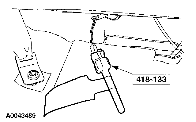
13. Remove the restraint system diagnostic tool from the vehicle harness side of the passenger air bag module electrical connector.
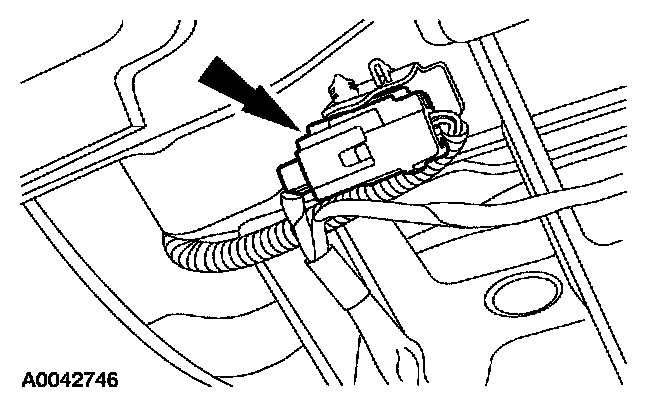
14. NOTE: The Expedition is shown, the Navigator is similar.
Connect the passenger air bag module electrical connector.
15. Close the glove compartment.

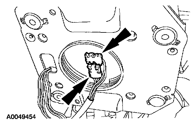
16. Remove the restraint system diagnostic tools from the clockspring electrical connector at the top of the steering column.
Navigator vehicles

17. Connect the driver air bag module accessories electrical connector to the connector end at the top of the clockspring.
18. CAUTION: The clockspring electrical connectors are unique and cannot be reversed when connected to the driver air bag module. Match the electrical connector key to the keyway in the driver air bag module. Do not force the electrical connectors into the driver air bag module.
Connect the driver air bag module electrical connectors as noted during removal.
- Position the driver air bag module to the steering wheel.
Expedition vehicles
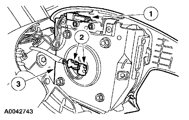
19. Position the driver air bag module to the steering wheel.
1 Connect the horn switch electrical connector.
2 CAUTION: The clockspring electrical connectors are unique and cannot be reversed when connected to the driver air bag module. Match the electrical connector key to the keyway in the driver air bag module. Do not force the electrical connectors into the driver air bag module.
Connect the driver air bag module electrical connectors as noted during removal.
3 Position the driver air bag module to the steering wheel.
All vehicles
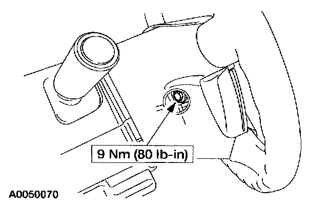
20. Install the two driver air bag module bolts (one shown).
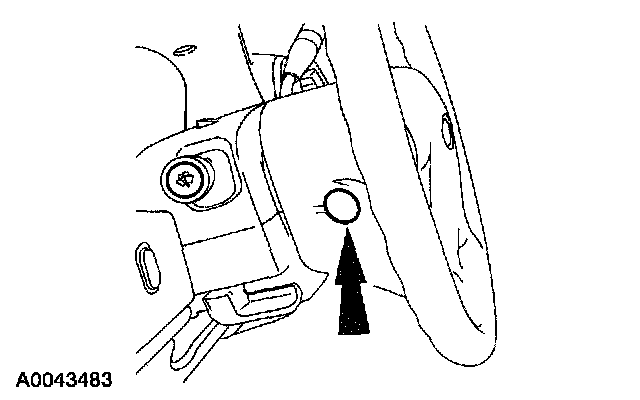
21. Install the two steering wheel back cover plugs (one shown).
22. Connect the battery ground cable.
23. WARNING: Restraint system diagnostic tools are for service only. tools must be removed prior to operating the vehicle over the road. Failure to remove restraint system diagnostic tools could result in injury and possible violation of vehicle safety standards.
With all the restraint system diagnostic tools removed, prove out the supplemental restraint system (SRS). Prove Out Procedure
Vehicles with safety canopies
24. Check the active restraint system for correct operation.