Part 1 - 37
ASSEMBLY
Transmission
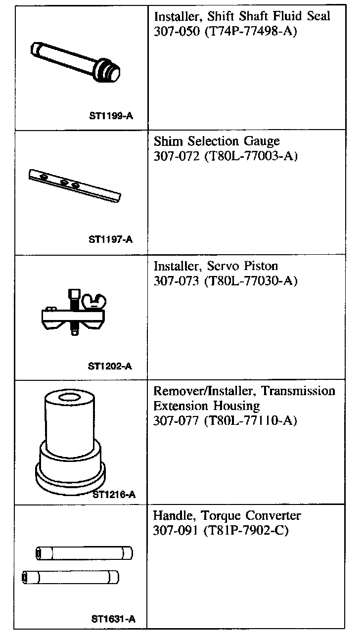
Special Tool(s)
Part 1 Of 3:

Part 2 Of 3:
Part 3 Of 3:

Material:

CAUTION: Before beginning assembly, carry out and inspect the following:
When building up subassemblies and assembling the transmission, ALWAYS use new gaskets and seals.
All fasteners must be tightened to the torque specification indicated.
When building up subassemblies, each component part should be lubricated with clean transmission fluid. It is also good practice to lubricate the subassemblies as they are installed in the case.
Needle bearings, thrust washers and seals should be lightly coated with petroleum jelly during subassembly buildup or transmission assembly.
Many components and surfaces in the transmission are precision machined. Careful handling during disassembly, cleaning, inspection and assembly can prevent unnecessary damage to machined surfaces.

1. Use the special tools to install the rear case bushing if removed.
1 Position the rear case bushing and the special tool inside the case.
2 Assemble the special tools through the back of the case.
2. Place the transmission in the vertical position.
3. Coat the No. 9 case rear bearing with petroleum jelly and install on the case boss.

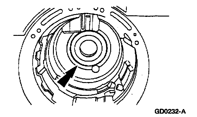
4. CAUTION: Be sure the No. 7 needle bearing and direct clutch hub are installed as shown. Internal damage and shift problems may occur.
Install the output shaft and output shaft ring gear.

5. Install the No.8 bearing.


6. Install the direct clutch.

7. NOTE: The reverse band support retaining ring is used for assembly purposes during production. The reverse band support retaining ring is not required during assembly, it will not affect the operation of the transmission.
Install the reverse band support retaining ring.

8. NOTE: Make sure the band is seated on the anchor pins.
Install the reverse band.
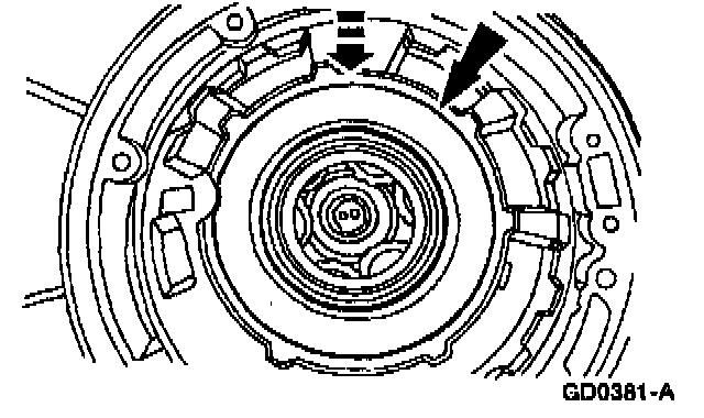
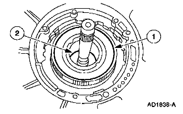
9. NOTE: The planetary assembly and planetary gear support cannot be installed unless the notch cut in the planetary gear support is aligned with the overdrive band anchor pin.
NOTE: The top of the planetary gear support must be below the snap ring groove.
Install the planetary assembly and planetary gear support as a unit.
^ Rotate the output shaft to fully seat the planetary assembly.
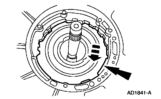
10. NOTE: The planet support spring must be compressed and installed below the snap ring groove. When the planet support spring is installed correctly both ends of the spring will be visible.
Install the case to planet support spring located at the 1 o'clock position.

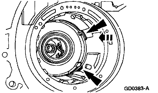
11. Install the center support retaining ring.
^ Reference the retaining ring tabs to the band anchor pin location.

12. Install the forward clutch sun gear, No. 5 forward clutch sun gear bearing and the reverse sun gear.

13. Install the No. 4 forward clutch hub bearing.

14. Install the intermediate stub shaft.

15. Install the forward clutch hub and the No. 3 forward clutch hub front bearing.

16. Install the forward clutch assembly.
17. NOTE: Make sure the reverse clutch cylinder lugs are completely seated in the notches of the reverse sun gear.
Install the reverse clutch cylinder assembly.
1 Install the reverse clutch cylinder assembly.
2 Install the No. 2 forward clutch bearing.

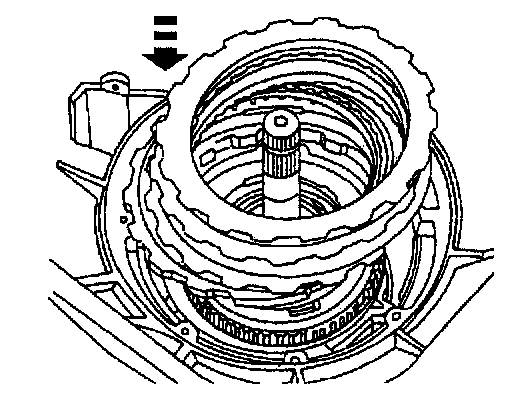
18. Install the overdrive band.
^ Position the overdrive band pocket onto the anchor pin.


19. Install the overdrive servo spring.
1 Install the overdrive servo piston return spring.
2 Install the overdrive servo piston.

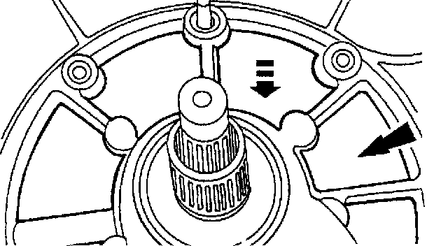
20. Verify the tip of the piston assembly engages the pocket of the overdrive band.
21. Using the special tool, compress the overdrive servo assembly and install the overdrive servo
22. Install the intermediate clutch pressure plate.
23. NOTE: Before assembly, soak the new clutch discs in clean automatic transmission fluid for 15 minutes.
Install the intermediate clutch pack and selective steel plate.
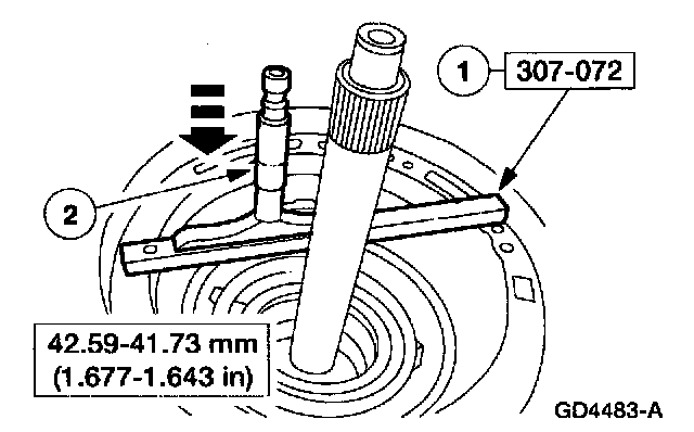
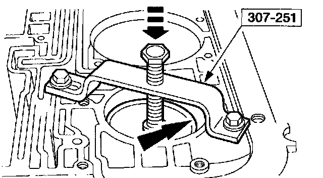
24. Using the special tool, check the intermediate clutch clearance.
1 Position the special tool on the pump case mounting surface.
2 Maintaining downward pressure, use a depth micrometer to measure and verify intermediate clutch clearance is within specification.
If the intermediate clutch is not within specification, install a correct selective plate.
Selective Steel Plates
Part 1 Of 2:

Part 2 Of 2:

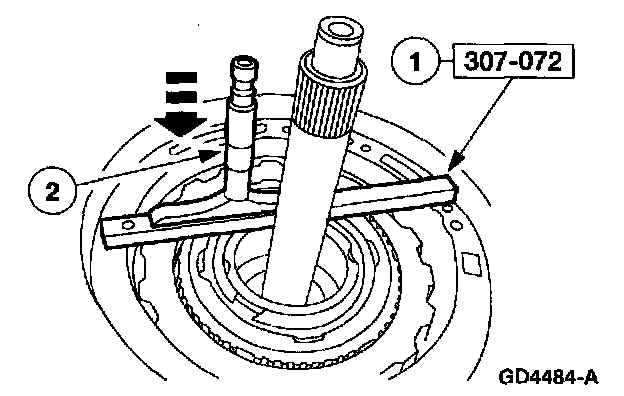
25. Using the special tool, measure end clearance for the No. 1 front pump thrust washer.
1 Position the special tool on the pump case mounting surface.
2 Maintaining downward pressure, use a depth micrometer to measure end play clearance.
Use the No. 1 thrust washer chart to select the correct washer.

No.1 Thrust Washer Chart
26. If equipped, install the intermediate clutch anti-rattle clip.

27. Install the intermediate clutch return spring support with the lip facing upward and the wave spring.
1. Install the intermediate clutch return spring support.
2. Install the wave springng

28. Install the No. 1 front pump support thrust washer.
^ Use petroleum jelly to hold the washer in place.

29. NOTE: The alignment pin is a fabricated M8 x 1.25 mm (0.05 in) bolt with the head removed.
Install an alignment pin at the top of the case.

30. NOTE: Make sure the gasket is positioned correctly and the case passages are not covered.
Install the pump gasket.
31. NOTE: To aid assembly, shake the input shaft while pushing down on the pump.
Install the pump assembly.
32. Remove the alignment pin and install the front pump bolts.
^ Alternate bolt tightening to set the pump.

33. Rotate the transmission to the horizontal position.
34. Install the parking pawl.
1 Position the parking pawl return spring.
2 Position the parking pawl.
3 Install the parking pawl shaft.

35. Install a new extension housing gasket and the extension housing.
1 Position the extension housing.
2 Install the four bolts and two nuts.

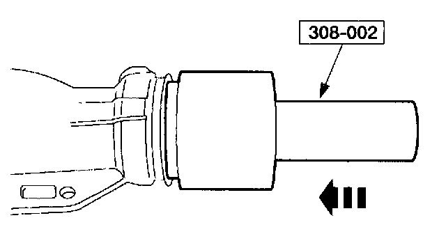
36. Using the special tool, install a new extension housing seal.
37. Install the Output Shaft Speed (OSS) sensor.
1 Position the OSS sensor.
2 Install the bolt.
