Steps 47-92
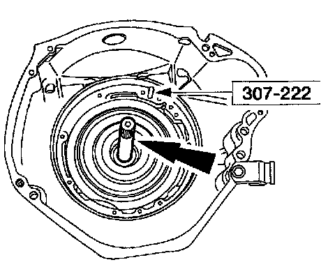
47. Install the input shaft with long splined end first and install the special tool.

48. NOTE: Lightly lubricate the thrust washer and bearing with petroleum jelly to hold it in place during assembly.
Install the No. 1 pump thrust washer and the No. 2A overdrive sun gear thrust bearing.

49. CAUTION: Pump assemblies are vehicle-dependent. Using the wrong pump will cause transmission failure.
CAUTION: Fully seat the front pump assembly using hand pressure only. Do not use bolts to draw the front pump assembly into the case.
CAUTION: Tighten the bolts alternately to avoid possible damage.
NOTE: Clock position is viewed looking into the converter housing with the top of the transmission in the 12 o'clock position.
Install the front pump assembly with the filter inlet tube bore in the 6 o'clock position. Fully seat the front pump assembly using hand pressure only. When the pump is fully seated, remove the special tool.

50. CAUTION: Discard the old washers.
Install the bolts with new rubber-coated washers. Tighten the bolts alternately in a crisscross pattern.

51. CAUTION: Remove the input shaft prior to rotating the transmission.
Remove the input shaft.

52. Using the special tool, install the manual control lever seal.

53. Install the manual control lever shaft assembly.
1 Install the manual control lever shaft assembly.
2 Install and seat the manual lever shaft retaining pin below the case surface.
3 NOTE: Use a crescent wrench on the manual control lever or outer flats of the manual control lever shaft assembly when installing the inner manual valve detent lever nut.
Install the parking pawl actuating rod, the inner manual valve detent lever and the nut onto the manual control lever shaft assembly.
4 NOTE: The manual control valve detent lever spring must be on the inner manual valve detent lever and the detent lever pin must align with the manual shift valve.
Install the manual control valve detent lever spring and the bolt.

54. Install the park pawl.
1 Install the parking pawl shaft.
2 Install the parking pawl.
3 Install the parking pawl return spring.

55. CAUTION: The Torx screw has a thread-locking compound. If the screw is removed, it must be discarded and a new one installed.
If removed, install the parking pawl abutment with a new Tory screw.

56. NOTE: Make sure the dimple on the parking guide support plate is facing inward and the parking pawl actuating rod is in the parking rod support plate slot.
Install the parking rod guide plate.
1 Install the parking rod guide plate.
2 Install the bolts.

57. Install a new orifice lube plug in the rear of the case. Using a 12 mm (0.48 inch) socket, tap the orifice lube plug into the back of the transmission.

58. Check to make sure that the orifice lube plug is fully seated into the back of the transmission.

59. CAUTION: The extension must have a shoulder or a boss cast in it to hold the orifice lube plug in the back of the case. If the wrong extension housing is used the plug will fall out and cause transmission failure.
Inspect the extension housing for the correct application.

60. CAUTION: The extension must have a shoulder or a boss cast in it to hold the orifice lube plug in the back of the case. If the wrong extension housing is used the plug may become loose and/or fall out and cause transmission damage.
NOTE: Lightly lubricate the gasket with petroleum jelly to hold it in place during assembly.
Install the new extension housing gasket.
1 Verify that the extension has a shoulder cast in it.
2 Install the new extension housing gasket.

61. Install the extension housing, the eight bolts, and the stud.

62. CAUTION: Prior to installing the extension housing bushing, inspect the extension housing counter bore for burrs. If necessary, remove the burrs with an oil stone. Damage to the new bushing may occur.
NOTE: Extension housing bushing is vehicle-dependent.
Align the extension housing bushing in the extension housing so that the slots are in the 2 o'clock and 7 o'clock position.

63. Using the special tool, install the extension housing bushing.

64. NOTE: Extension seal is vehicle-dependent.
Using the special tool, install a new extension housing seal.

65. Tighten the center support assembly, and the intermediate/overdrive cylinder assembly feedbolts.

66. NOTE: The steel EPC check ball has a 6.35 mm (0.25 inch) diameter and is smaller than the other check balls.
Install the spring and the steel EPC check ball.
Part 1 Of 2:

Part 2 Of 2:

67. CAUTION: Use care not to damage the rubber check balls.
Install the rubber check balls.

68. CAUTION: Using the incorrect gasket will cause damage to transmission.
Install a new separating plate-to-case gasket on the separating plate.

69. NOTE: Check the placement of the steel EPC check ball under separator plate.
Install the valve body separator plate.

70. Install the separating plate reinforcing plate, with the stamped word UP visible, and install the bolts.

71. CAUTION: Using the incorrect gasket will cause damage to the transmission.
Install a new main control-to-separating plate gasket.

72. Install the solenoid screen assembly by pushing it in and rotating it to lock.

73. NOTE: Prior to installing the solenoid body assembly, coat the case connector bore with petroleum jelly or equivalent.
Install the solenoid body assembly with the nut and the Torch bolts finger-tight.

74. Install the main control valve body, aligning the manual shift valve with the inner manual valve detent lever. Install the nuts and the bolts finger-tight.

75. Install the accumulator body with the nuts and the bolts finger-tight.

76. Tighten all accumulator body, upper and lower control body and solenoid body nuts and bolts.

77. CAUTION: Mixing the 4x2-style and 4x4-style transmission fluid filters and transmission pan assembly components can cause transmission damage.
Select the appropriate 4x2-style or 4x4-style filter assembly and transmission pan.
1 4x2 filter and pan application.
2 4x4 filter and pan application.

78. CAUTION: Make sure the pump bore is clean and the oil filter seal has been removed. Damage to new filter and seal can occur.
NOTE: Prior to installation, lightly lubricate the seal with clean automatic transmission fluid.
Install a new fluid filter and seal assembly into the pump bore until seated.

79. NOTE: Do not discard the gasket unless damaged. This is a reusable gasket.
NOTE: Apply a light coat of petroleum jelly to hold the gasket to the fluid pan.
Position the gasket onto the clean fluid pan. Make sure the magnet is positioned over the dimple in the fluid pan.

80. CAUTION: Mixing the 4x2-style and 4x4-style transmission fluid filters and transmission pan assembly components can cause transmission damage.
Install the correct pan with gasket for this application. Alternately tighten the bolts.

81. With the transmission in NEUTRAL, install and adjust the digital Transmission Range (TR) sensor.
1 Install the digital TR sensor.
2 Loosely install the bolts.

82. Using the special tool, align the TR sensor.

83. Tighten the bolts and remove the special tool.
84. Make sure that the cooler bypass valve (CBV) has been cleaned and flushed.

85. CAUTION: Failure to correctly install the new rubber-coated sealing washers will result in transmission fluid leaks.
Install the new rubber-coated sealing washers and the new cooler line case fittings.
1 Install one rubber-coated sealing washers on each cooler line case fittings.
2 Install new cooler line case fittings into their respective ends of the CBV assembly.
3 Install one rubber-coated sealing washers on each cooler line case fittings.

86. CAUTION: Do not overtighten. Damage to the sealing washers can occur.
Install the CBV with the front (inlet) and the rear (outlet) cooler line case fitting.

87. CAUTION: Use care when installing the sensor, damage to the O-ring seal can result in a leak.
Install the Output Shaft Speed (OSS) sensor.
1 Lubricate O-ring seal and install the OSS.
2 Install the bolt.

88. CAUTION: Use care when installing the sensor, damage to the O-ring could result in a leak.
If removed, install the Turbine Shaft Speed (TSS) sensor.
1 Lubricate O-ring and install the TSS.
2 Install the bolt.

89. NOTE: The input shaft is vehicle-dependent.
With the fluid pan facing down, install the input shaft with the long splined end first.

90. CAUTION: Do not damage the fluid pump gear O-ring when installing torque converter.
CAUTION: Make sure the converter hub is fully engaged in the front pump support and gear and rotates freely. Do not damage the hub seal.
CAUTION: If the torque converter slides out, the hub seal may be damaged.
Lubricate the converter hub with clean automatic transmission fluid.

91. CAUTION: Use care when installing the torque converter to avoid damage to the front pump stator support seal.
NOTE: Check the converter crankshaft pilot for nicks or damaged surfaces that can cause interference when installing the transmission to the engine. Check the converter impeller hub for nicks or sharp edges that can damage the pump seal.
NOTE: Carry the torque converter with the Torque Converter Handles held in the 6 o'clock and 12 o'clock positions.
Using the special tools, install the torque converter. Push and rotate the converter onto the front pump assembly until it bottoms out.

92. Check the seating of the torque converter.
1 Place the straightedge across the converter housing.
2 Make sure there is a gap between the converter pilot face and the straightedge.
3 Remove the special tools.