Disassembly
TransmissionPart 1 Of 3:

Part 2 Of 3:

Part 3 Of 3:

Special Tool(s)
NOTE: Refer to the Disassembled Views for component location and orientation.

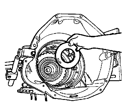
1. Using the special tools, remove the torque converter from the transmission.

2. CAUTION: The Turbine Shaft Speed Sensor (TSS) must be removed or damage to the sensors will occur.
Remove the Turbine Shaft Sensor (TSS).
1 Remove the bolt.
2 Remove the Turbine Shaft Sensor (TSS).

3. CAUTION: The Output Shaft Speed Sensor (OSS) will need to be removed or damage to the sensors will occur.
Remove the Output Shaft Speed Sensor (OSS).
1 Remove the bolt.
2 Remove the Output Shaft Speed Sensor (OSS).
4. Mount the transmission to a suitable stand.

5. CAUTION: The input shaft and overdrive planet assembly are replaced as mating components.
Remove the input shaft.

6. CAUTION: The sealing washers may fall off the cooler line case fittings.
NOTE: The bolts are part of the Cooler Bypass Valve (CBV) assembly.
Remove the cooler bypass valve.
1 Remove the cooler line case fittings.
2 Remove the cooler bypass valve.

7. Remove the Transmission Range (TR) sensor.
1 Remove the bolts.
2 Remove the Transmission Range (TR) sensor.

8. NOTE: Do not discard the gasket unless damaged. This is a reusable gasket.
Remove the transmission fluid pan and the gasket.

9. CAUTION: If the seal remains in the pump bore, remove it carefully with a small screwdriver so as not to scratch or damage the aluminum bore.
NOTE: After removal, discard the filter and seal assembly.
Remove the filter and seal assembly by carefully pulling and rotating the filter as necessary.

10. Remove the bolts, nuts and the accumulator body.

11. NOTE: Do not remove the lower-to-upper main control valve body assembly bolts. Keep the main control valve bodies attached as an assembly.
Remove the main control valve body.
1 Do not remove the two lower-to-upper main control valve body assembly bolts.

12. Remove the bolts, nut and the solenoid body assembly, by pushing the solenoid body connector upward to help separate the assembly from the case bore.

13. Remove the solenoid screen assembly by rotating and pulling.

14. CAUTION: The steel Electronic Pressure Control (EPC) check ball is spring-loaded under the valve body separator plate.
Remove the separator plate reinforcing plate and the valve body separator plate with the two gaskets. Discard both gaskets.

15. NOTE: The steel EPC check ball has a 0.5 mm (0.02 inch) diameter and is smaller than the other check balls.
Remove the steel EPC check ball and spring.

16. CAUTION: Use care not to damage the rubber check balls. Transmission shift problems can occur.
Using a small screwdriver, carefully remove the eight rubber check balls.

17. Using a plastic or rubber-headed hammer, tap gently on the intermediate band servo assembly piston. The downward force will compress the spring. The upward momentum of the spring will force the assembly to be released from the case bore.

18. CAUTION: After removal, discard the feedbolts. The bolts will not retain torque specification if reused.
Remove and discard the feedbolts.

19. Remove the pump bolts and discard the washers.

20. NOTE: The special tools should be installed into the pump threaded holes as shown.
Using the special tools. remove the pump.

21. NOTE: The No. 1 pump thrust washer and the No. 2A overdrive sun gear thrust bearing may stay with the pump.
Remove the No. 1 pump thrust washer.
1 Remove the No. 1 pump thrust washer.
2 Remove the No. 2A overdrive sun gear thrust bearing.
3 Remove the pump gasket and discard.

22. CAUTION: The coast clutch, overdrive ring gear, centershaft assembly must be removed as an assembly, using special service tool or damage to the overdrive one-way clutch can occur.
Using the special tool remove the coast clutch, overdrive ring gear, centershaft assembly.

23. NOTE: The No. 5 thrust bearing may remaining on the center shaft or the center support.
Remove the No. 5 overdrive center shaft thrust bearing assembly.

24. Remove the overdrive clutch pressure plate retainer snap ring.

25. NOTE: Tag the parts for identification during installation.
Remove the overdrive clutch pressure plate and the clutch pack.

26. Using the special tool, remove the intermediate/overdrive cylinder retaining ring.

27. CAUTION: During removal, do not misalign the intermediate/overdrive cylinder assembly in the case bore. This can damage the case bore.
Remove the intermediate/overdrive cylinder assembly.

28. Remove the intermediate clutch piston return spring.

29. CAUTION: During removal, do not misalign the center support in the case bore. This can damage the case bore.
Carefully remove the center support assembly.
30. Remove the No. 6 center support thrust washer.

31. NOTE: Tag the parts for identification during installation.
Remove the intermediate clutch rear pressure plate.
1 Remove the intermediate clutch pressure apply plate.
2 Remove the intermediate clutch pack.
3 Remove the intermediate clutch rear pressure plate.

32. Remove the intermediate band.

33. NOTE: When installing the special tool, each leg of the tool must be rotated separately to engage notches on the input shell prior to tightening the top cross bar.
Using the special tool, remove the direct clutch, forward clutch and input shell as an assembly.

34. Remove the reverse planet retaining ring.

35. Remove the reverse planet assembly, No. 10B, and the No. 11 reverse planet carrier thrust washers.

36. WARNING: Use care when removing the output shaft retaining ring. The output shaft can fall out. Do not reuse the output shaft retaining ring.
Remove the output shaft retaining ring.

37. Remove the output shaft ring gear and hub assembly.

38. WARNING: Use care not to drop the output shaft while rotating the transmission.
Remove the following parts as an assembly.
1 Reverse clutch pack (pressure plate, friction plate and seals).
2 Reverse clutch hub.
3 Low/reverse one way clutch assembly.

39. Using the special tools, remove the extension housing seal.

40. Using the special tool, remove the extension housing bushing.

41. Remove the eight bolts, one stud and the extension housing. Remove and discard the extension housing gasket.

42. NOTE: Be sure not to damage the output shaft drive sprocket speed sensor wheel or the park gear.
NOTE: The parking gear and output shaft drive sprocket speed sensor wheel are a press fit to the output shaft.
Remove the output shaft.

43. Remove the No. 13 thrust bearing.

44. Remove the plastic orifice lube plug form the rear of the case and discard.

45. Remove the five bolts retaining the low/reverse one-way clutch inner race to the case.

46. Remove the low/reverse one-way clutch inner race and the reverse clutch return spring assembly.

47. To remove the reverse clutch piston, reinstall the reverse clutch pressure plate and the reverse clutch pressure plate retainer snap ring to retain the reverse clutch piston.

48. Using compressed air, blow into the reverse clutch feed port to blow out the reverse clutch piston against the reverse clutch pressure plate.

49. Remove the reverse clutch pressure plate retainer snap ring, the reverse clutch pressure plate and the reverse clutch piston.

50. If required, remove the parking rod guide plate.

51. If required, remove the parking pawl.
1 Remove the parking pawl return spring.
2 Remove the parking pawl.
3 Remove the parking pawl shaft.

52. CAUTION: The Torx-head screw has a threadlocking compound and should be removed only if the case is being replaced. If the bolt is removed, it must be discarded and a new one installed.
If required, remove the parking pawl abutment.

53. NOTE: A No. 53 drill bit (1/16-inch) can be used instead to capture and remove the manual lever shaft retaining pin.
Using the special tool, remove the manual lever shaft retaining pin.

54. CAUTION: Use care not to damage the manual control lever bore.
NOTE: The manual control lever and manual control lever shaft are one piece.
Remove the manual control lever shaft assembly.
1 NOTE: Use a crescent wrench on the manual control lever or outer flats of the manual control lever shaft assembly when removing the inner manual valve detent lever nut.
Remove the nut, the inner manual valve detent lever and the parking pawl actuating rod.
2 Remove the manual control lever shaft assembly.
3 Remove the bolt and the manual control valve detent lever spring.

55. Using the special tool, remove the manual control lever seal.

56. NOTE: The short fluid inlet tube should be removed only if it is loose or damaged.
If required, remove the short fluid inlet tube.
57. Inspect the case assembly for cracks and stripped threads. Inspect the gasket surfaces and mating surfaces for burrs. Check the case vent assembly for obstructions and check all fluid passages for obstructions.
58. Inspect the case assembly bushing for scores. Check all parking linkage parts for wear or damage.
59. If the transmission case assembly thread is damaged, repair kits (helicoil) can be purchased from local jobbers. To repair a damaged thread, follow procedures furnished in the helicoil kit.