Assembly
Assembly
1. CAUTION: Do not omit the pinion bearing oil baffle; bearing failure can result.
If removed, position the baffle on the special tool.

2. Using the special tool, install the baffle.
3. NOTE: Always install new pinion bearings when installing new pinion bearing cups.
Lightly oil the new pinion bearing cups and pinion bearings with front axle lubricant.

4. Using the special tool, install the bearing cups.

5. NOTE: You must use the pinion bearings assembled step at final assembly.
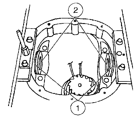
Assemble and position the special tools and the pinion bearings in the carrier housing.
1 Position the screw Adapter.
2 Position the aligning Adapter.
3 Position the pinion bearing.
4 Position the gauge disc Adapter.
5 Position the gauge block Adapter.
6 Position the pinion bearing.
7 Thread on the handle Adapter.

6. NOTE: This step duplicates final pinion bearing preload.
Tighten the special tool to the specification to simulate bearing preload.

7. NOTE: Offset the gauge block Adapter to obtain an accurate reading.
Rotate the gauge block Adapter several half-turns to make sure the pinion bearings seat correctly, and position the gauge block Adapter.

8. Install the special tool.
1 Position the special tool.
2 Install the differential bearing caps.
3 Install the bolts.

9. NOTE: Use only flat, clean drive pinion bearing adjustment shims.
NOTE: Selection of too thick a shim results in a deep tooth contact at final assembly of integral axle assemblies. Do not attempt to force the shim between the gauge block Adapter and the gauge tube Adapter. A slight drag indicates correct shim selection.
Use a drive pinion bearing adjustment shim as a gauge for shim selection.
^ Check the adjustment shim thickness between the gauge block Adapter and the gauge tube Adapter.
^ After determining the correct shim thickness, remove the special tools.

10. NOTE: You must use the same pinion bearings from the previous steps.
Install the pinion bearing.
^ Place the drive pinion bearing adjustment shim on the pinion gear.
^ Using a suitable press and the special tool, press the pinion bearing until it is firmly seated on the pinion gear.

11. Place a new drive pinion collapsible spacer on the pinion stem.

12. Install the outer pinion bearing.

13. Install the slinger.

14. NOTE: Coat the lips of the pinion seal with front axle lubricant.
Place the pinion seal on the special tool.

15. Place the special tool and seal in the pinion seal bore and drive the seal into place.
16. Lightly lubricate the pinion gear splines with front axle lubricant.

17. Position the drive pinion in the housing.

18. CAUTION: Never install the drive pinion universal joint flange with a hammer or power tools.
NOTE: Disregard the scribe marks if installing a new flange.
Align the index-marks and position the universal joint flange on the drive pinion.

19. Using the special tool, install the drive pinion universal joint flange.
20. Apply a small amount of lubricant to the washer side of the new pinion nut, and install the nut.


21. CAUTION: Do not loosen the pinion nut to reduce preload under any circumstance. If it is necessary to reduce preload, install a new drive pinion collapsible spacer and pinion nut.
Install the special tool, and tighten the pinion nut.
^ Rotate the pinion gear occasionally to make sure the pinion bearings are seating correctly. Take frequent pinion bearing torque preload readings by rotating the pinion gear with a Nm (inch-pound) torque wrench.

22. CAUTION: Use extreme care not to damage the aluminum differential carrier housing while carrying out the following procedure steps.
CAUTION: The special tools are marked LH and RH. Install them accordingly.
Install the special tools.

23. Install the differential case with the Differential Bearings Gauge in the differential carrier housing.

24. NOTE: Repeat this step until you obtain a consistent reading.
Measure the total end play.
1 Position the special tools.
2 Position the indicator tip on the machined surface and adjust it to measure full travel.
3 Push the differential case left and right (as far as possible).
4 Measure the total end play and record the reading on the Differential Bearing Shim Selection Procedure Worksheet, Line A.

25. Remove the special tools and the differential case.

26. Use a fine fiat file to remove any busts or nicks from the ring gear mounting surface.

27. Install the ring gear.
1 Position three bolts to align the holes in the ring gear and the differential case.
2 Using a suitable press, install the ring gear.

28. Install the remaining bolts.

29. Remove three adjacent bolts,,

30. CAUTION: Position the three empty bolt holes downward.
Position the differential case with the special tools into the differential carter housing.

31. Position the special tools.

32. Push and rock the ring gear into mesh with the pinion gear (zero backlash) and adjust the special tool to zero.

33. Move the ring gear away from the pinion gear as far as possible. Record the reading on the Differential Bearing Shim Selection Procedure Worksheet, Line B.

34. Remove the special tools.

35. Remove the differential case and the special tools.

36. NOTE: Measure both of the differential bearing stand heights prior to installing them on the differential case.
NOTE: Mark the left and right differential bearings before measuring them.
Clamp the special tool base in a soft jawed vise with the bearing mounting surface above the surface of the vise.

37. Position the differential bearing assembly in the special tool, and tighten the tool.

38. Measure the differential bearing stand height.
1 Invert the special tool and bearing assembly in the vise.
2 Use a depth micrometer to measure and record the differential bearing stand height.
^ Repeat the procedure for the other bearing.
39. Select appropriate differential bearing shims.


Differential Bearing Shim Selection Chart

40. Select the appropriate shim by the thickness or the stripe color.

Differential Shim Size Chart

41. Install the three bolts.

42. CAUTION: Press against the bearing inner core only.
Using a suitable press and the special tool, install the differential bearings.
1 Position the appropriate differential bearing (RH or LH).
2 Using a suitable press and the special tool, install the differential bearing.
^ Repeat the procedure for the other differential bearing.

43. NOTE: Make sure the indicator needle is in the spreader adapter hole.
Install the special tools.

44. CAUTION: Overspreading can damage the axle housing.
Spread the axle housing to the specification.
^ Remove the Dial Indicator.
45. CAUTION: Never attempt to drive the differential bearing shim in place. Permanent damage to the machined axle housing surfaces can occur.
If removed, position the differential bearing shims.
1 Apply a light coating of long life grease to one side of the differential bearing shims to help hold them in place.
2 Position the differential bearing shims.

46. NOTE: Push the differential case downward to fully seat the differential bearing cups in the axle housing.
Position the differential case assembly.
1 Position the differential bearing cups on the differential bearings.
2 Lower the differential case assembly in place between the differential bearing shims.

47. Install the bearing caps in their original positions and tighten with the housing still spread.
1 Position the bearing caps.
2 Install the bolts.
3 Remove the special tool.

48. Install the special tool.

49. Measure the ring gear backlash at four places to obtain a consistent reading.

50. NOTE: If the backlash is not within the specifications, correct it by increasing the thickness of one differential bearing shim and decreasing the thickness on the other differential bearing shim by the same amount.
To increase the backlash, install a thicker differential bearing shim and a thinner differential bearing shim as shown.

51. To decrease the backlash, install a thicker differential bearing shim and a thinner differential bearing shim as shown.

52. CAUTION: Remove all of the old liquid gasket, and make sure the machined surfaces are free of oil before applying the new silicone rubber.
CAUTION: Install the axle housing tube within 15 minutes of applying the silicone or it will be necessary to remove and reapply new sealant. If possible, allow one hour before filling with lubricant to make sure the silicone sealant has cured.
CAUTION: Do not allow any silicone rubber to squeeze inside during assembly.
Assemble the axle housing tube
^ Align the bolt holes and position the axle tube
^ Position the axle identification tag
^ Install the bolts.

53. Examine the axle shaft seal and bearing surface for damage If necessary, polish the bearing surface with fine crocus cloth

54. Insert the axle shafts and engage them with the side gears

55. NOTE: Do not reuse the old snap rings
Push in on the axle shafts and install new snap rings
56. Remove the axle assembly from the Holding Fixture and place it on the bench

57. CAUTION: Remove all of the old liquid gasket, and make sure the machined surfaces are free of oil before applying the new silicone rubber.
CAUTION: Install the differential housing cover within IS minutes of applying the silicone, or it will be necessary to remove and reapply new sealant. If possible, allow one hour before filling with lubricant to make sure the silicone sealant has cured.
Fill the sealing groove on the differential housing cover with silicone gasket and sealant.

58. Install the differential housing cover.
1 Position the differential housing cover.
2 Install the bolts.

59. Fill the differential carrier housing, and install the fill plug.
^ Use front axle lubricant.
^ Be sure to tighten both the drain and fill plugs.
60. Install the front drive axle assembly.