Assembly
Assembly
Assembly, Differential Case and Ring Gear-Traction-Lok
1. Prelubricate each steel clutch plate and soak all friction plates with 118 ml (4 ounces) of friction modifier for at least 15 minutes.

2. NOTE: Do not mix the differential clutch packs or shims from one side with the opposing side.
Assemble the differential clutch packs (without the shims or Belleville springs) on the respective side gears.

3. Clamp the bolt head of the special tool in a vise. Install the differential clutch pack and the differential side gear (without the shims or Belleville spring) on the gauge.

4. Position the special tool on top of the differential clutch pack.

5. Install the special tool over the disc and differential clutch pack.
6. Install the nut over the top and base stud.

7. NOTE: A maximum of two shims can be used on each clutch pack.
Select and insert the thickest feeler gauge blade that will enter between the tool and the differential clutch pack. Subtract 0.010 inch from the reading to obtain the thickness of the new clutch shim. Select the correct shim and remove the special tool.

Selective Shims

8. NOTE: The concave side of the Belleville spring must face up and against the thrust face of the differential case.
Place the shim and the Belleville spring on the differential clutch pack.

9. Insert the differential clutch packs with the shims and Belleville springs and differential side gears into the differential case.

10. NOTE: If necessary, insert the dowel bar in the nut bore to keep the nut from turning as the hex screw is tightened.
Assemble the special tool in the differential case.
1 Position the special tool in the bottom side gear bore.
2 Position the special tool in the top side gear bore and hold it in place.
3 Install the special tool and tighten it two turns after it contacts the bottom step plate.

11. NOTE: Coat both sides of the differential pinion thrust washers with rear axle lubricant.
Position the differential pinion gears and thrust washers in the differential case window so they mesh with the differential side gear teeth.

12. NOTE: It may be necessary to loosen or tighten the special tool forcing screw to allow the differential side gears to rotate.
Insert the special tool into the pinion shaft bore and turn the differential case. This will move the differential side gears and position them in the differential case. Rotate the differential case until the pinion mating shaft holes are aligned with the differential pinion gears.

13. Loosen the special tool forcing screw and remove the special tool from the differential case. Install a new differential pinion shaft and bolt in the differential case.

14. If removed, install new differential carrier bearings.

15. Using the special tools, check the torque required to rotate on differential side gear.
1 Install the special tools as shown.
2 If the original clutch plates are used, the initial breakaway torque must be within specification. The rotating torque required to turn the differential side gear with new clutch plates, may vary.

16. Install the differential ring gear.
1 Place the differential ring gear on the differential case.
2 Hand start three bolts to align the ring gear to the differential case.
3 Place the differential case and ring gear fin the press bed with the ring gear teeth facing down.
4 Press the ring gear into place on the differential case.

17. install the ring gear bolts and tighten to specification.
Assembly, Differential Case and Ring Gear-Conventional

18. NOTE: Coat the differential side gears and differential side gear thrust washers with rear axle lubricant.
Position the differential thrust washers on the differential side gears.

19. Position the differential side gears and thrust washers in the differential case.

20. NOTE: Coat the differential pinion thrust washers and differential pinion gears with rear axle lubricant.
Assemble the differential pinion thrust washers and the differential pinion gears.

21. Engage the differential pinion gears opposite the differential side gears.

22. Rotate the differential pinion gears to align with the differential pinion shaft bore.

23. Insert the differential pinion shaft.

24. NOTE: If a new pinion shaft lock bolt is unavailable, coat the threads with sealer prior to installation.
Install a new differential shaft lock bolt and torque to specification.

25. Using the special tool, install the differential bearings.

26. Install the differential ring gear.
1 Place the differential ring gear on the differential case.
2 Hand start three bolts to align the holes in the differential ring gear and the differential case.
3 Place the differential case and the differential ring gear on the press bed with the ring gear facing down.
4 Press the ring gear into place.

27. NOTE: Apply sealer to the threads of the ring gear bolts.
Install the differential ring gear bolts and tighten.

Final assembly-All Differentials
28. Position the inner and outer bearing cups in their respective bores.
1 After positioning the bearing cups in the bores, place the special tool on the inner bearing cup.
2 Place the special tool on the outer bearing cup.
3 Install the special tools.

29. Tighten the special tool to seat the bearing cups in the bores.

30. NOTE: If a feeler gauge of the specification shown can be inserted between a cup and the bottom of its bore at any point around the cup, the cup is not correctly seated.
Make sure the differential pinion bearing cups are correctly seated.

31. NOTE: Apply a light film of lubricant on the front and rear pinion bearings.
Install the pinion bearings and special tools as shown.

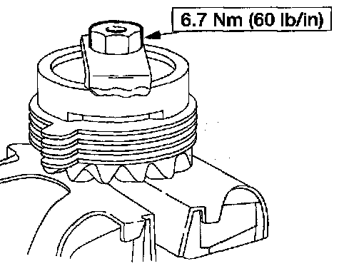
32. NOTE: This step duplicates pinion bearing preload.
Thread the special tool onto the screw and tighten to the specification shown.

33. NOTE: The special tool must be offset to obtain an accurate reading.
Position the special tool.

34. Install the special tool.

35. NOTE: Drive pinion bearing adjustment shims must be flat and clean.
NOTE: A slight drag should be felt for correct shim selection. Do not attempt to force the pinion shim between the Gauge Block and the Gauge Tube. This will minimize selection of a pinion shim thicker than required, which results in a deep tooth contact in the final assembly of integral rear axle assemblies.
Use a drive pinion bearing adjustment shim a. a gauge for shim selection.
^ After the correct shim thickness has been determined, remove the special tools.

36. Using the special tools, press the inner pinion bearing and pinion shim until they are firmly seated on the pinion.

37. Place a new drive pinion collapsible spacer on the pinion shaft against the pinion stem shoulder.

38. Install a new outer pinion bearing, and rear axle drive pinion shaft oil slinger.

39. CAUTION: Installation without the correct tool can result in early seal failure. If the rear axle drive pinion seal becomes cocked during installation, remove it and install a new one.
CAUTION: Coat the lips of the rear axle drive pinion seal with grease.
Place the drive pinion oil seal on the special tool and drive the seal into place.

40. NOTE: Lubricate the pinion flange splines with rear axle lubricant.
Install the drive pinion in the drive pinion carrier bore from inside the rear axle housing. Seat the drive pinion with a plastic hammer.

41. NOTE: Disregard the scribe marks if a new pinion flange is being installed.
Align the pinion flange with the drive pinion shaft.

42. With the drive pinion in the axle housing, install the pinion flange using the special tool.

43. Position the new pinion nut.

44. CAUTION: Under no circumstances is the pinion nut to be backed off to reduce preload. If reduced preload is required, a new drive pinion collapsible spacer and pinion nut must be installed.
CAUTION: The pinion flange holding tool must be removed before preload readings can be taken.
Using the special tool, tighten the pinion nut.
^ Rotate the pinion occasionally to make sure the drive pinion bearings are seating correctly.
^ Install a Nm (inch-pound) torque wrench on the pinion nut.
^ Rotating the pinion through several revolutions, take frequent drive pinion bearing torque preload readings until the original recorded preload reading is obtained.
^ If the original recorded preload is below specification, tighten to the appropriate specification for used bearings. If the preload is above specification, tighten the nut to the original readings as recorded.
45. With the pinion depth set and the pinion installed, place the differential case in the rear axle housing.

46. Install a shim as shown on the left side.

47. NOTE: Apply pressure toward the left side to make sure the left bearing cup is seated.
Install the left bearing cap and loosely install the bearing car bolts.

48. Install progressively larger shims on the right side until the largest shim selected can be installed by hand.

49. Install the right side bearing cap and tighten the bolts.

50. Rotate the differential case to make sure it rotates freely.


Measuring backlash
51. Using the special tools, measure and note the differential ring gear backlash.
^ If backlash is within the specification, refer to Backlash within specification.
^ If a zero backlash condition occurs, refer to Zero backlash.
^ If backlash is not within the specification, refer to Backlash not within specification.

Zero backlash
52. If a zero backlash condition occurs, add 0.51 mm (0.020 inch) to the RH side and subtract 0.51 mm (0.020 inch) from the LH side to allow backlash indication. Measure the backlash.

Backlash not within specification
53. To increase or decrease backlash, remove the differential bearing caps and install a thicker shim and a thinner shim accordingly.
^ If backlash is not within the specification, increase the thickness of one differential bearing shim and decrease the thickness of the other differential bearing shim by the same amount.

54. Rotate the differential assembly several times to verify that the differential bearings seated correctly.

55. Using the special tools, recheck the backlash.
^ If backlash is within the specification, refer to Backlash within specification. If backlash is not within the specification, repeat Backlash not within specification.
Backlash within specification
56. Remove the bolts and the differential bearing caps.

57. To establish differential bearing preload, increase both left and right differential bearing shim sizes by the specification shown.

58. Install the differential bearing caps and bolts.

59. Using the special tools, recheck the backlash.

60. Remove the axle assembly from the holding fixture and install the torque arm.

61. NOTE: The differential housing cover must be installed within 15 minutes of application of the silicone, or new sealant must be applied. If possible, allow I hour before filling with lubricant to make sure the silicone sealant has cured correctly.
Install the differential housing cover and tighten the differential housing cover bolts.