Disassembly and Assembly, Front Drive Halfshafts
Halfshaft
Special Tool(s)
Disassembly
1. Remove the halfshaft from the vehicle.

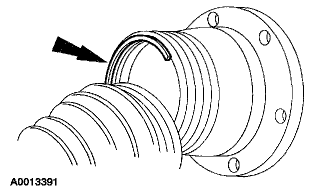
2. CAUTION: Do not damage the boot.
Remove the boot clamps.

3. Separate the boot from the inboard CV joint housing.

4. Remove the retaining ring.

5. Remove the inboard CV joint housing.

6. Index-mark the inner race and ball cage.

7. Remove the six balls.

8. Remove the snap ring.

9. Remove the inner race and the ball cage.

10. Remove the inboard boot.

11. Remove the boot clamps.

12. Remove the outboard boot.
13. NOTE: If the grease is contaminated, clean and inspect the joint for wear. Install a new outboard CV joint and interconnecting shaft assembly if worn/damaged.
Check the grease for contamination.
Assembly

1. Position the outboard boot on the shaft.

2. Pack the outboard CV joint with 165 grams (5.82 ounces) of grease.
1 Use constant velocity joint grease or equivalent provided in the boot kit.
2 Spread any remaining grease from the kit evenly inside the boot.

3. Install the outboard boot.
1 Clean the boot mounting surface.
2 Seat the boot in the joint boot groove.

4. Make sure a shaft groove is exposed by positioning the small end of the boot in the groove closest to the constant velocity joint housing.

5. Position the boot clamps.

6. NOTE: Tighten the through-bolt until the tool is in the closed position.
Using the special tool install the two boot clamps.

7. Position the boot clamp on the shaft.

8. Position the inboard boot on the shaft.

9. Position the ball cage on the shaft with the tapered end facing the boot.

10. NOTE: Align the index marks.
Position the inner race on the shaft with the counterbored end facing the boot.

11. Install the snap ring.

12. Lubricate and position the six balls.
^ Use constant velocity joint grease or equivalent provided in the boot kit.

13. Fill the inboard CV joint housing with 235 grams (8.29 ounces) of grease.
^ Use constant velocity joint grease or equivalent provided in the boot kit.

14. Make sure a shaft groove is exposed by positioning the small end of the boot in the groove closest to the constant velocity joint housing.

15. Position the boot clamp on the inboard CV joint housing.

16. Position the inboard CV joint housing on the ball and race assembly.
17. Install the retaining ring.

18. Remove any excess grease from the mating surface. Seat the boot in the joint boot groove.

19. Set the halfshaft assembled length to specification.

20. CAUTION: Do not damage the boot.
Insert a dull screwdriver blade under the boot to release the pressure.

21. NOTE: Tighten the through-bolt until the tool is in the closed position.
Using the special tool, install the two boot clamps.

22. NOTE: Maintain a clean work surface.
Compress the integrated wheel end disconnect on the bench to collapse the vacuum chamber.

23. While the integrated wheel end disconnect is collapsed, install a vacuum cap on the vacuum port.

24. CAUTION: Do not install the integrated wheel end disconnect in the knuckle. It must be installed on the outer constant velocity joint housing.
Install the integrated wheel end disconnect on the outer constant velocity joint housing
25. CAUTION: Verify the spline engagement by checking for spline lash before installing the halfshaft nut.
Install the halfshaft in the vehicle.