Camshaft Position Sensor: Service and Repair
CAUTION: Prior to the removal of the Camshaft Position (CMP) sensor, set No. 1 cylinder to 0° Top Dead Center (TDC) of compression stroke. Then note the position of the camshaft position sensor electrical connector. The installation procedure requires that the connector be located in the same position.REMOVAL
1. Disconnect battery ground cable.
NOTE: When the battery has been disconnected and reconnected, some abnormal drive symptoms may occur while the Powertrain Control Module (PCM) relearns its adaptive strategy. The vehicle may need to be driven 16 km (10 miles) or more to relearn the strategy.
2. Disconnect fuel charging wiring connector from stator assembly.
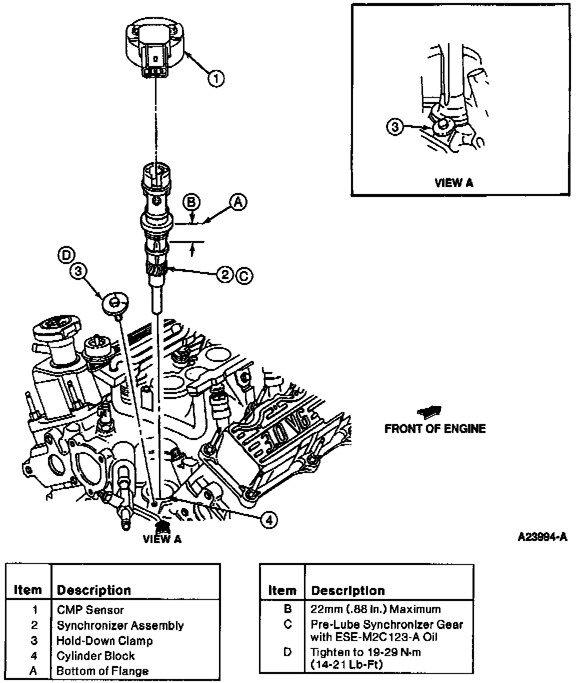
3. Remove the CMP sensor retaining screws and camshaft position sensor from synchronizer assembly.
4. If synchronizer assembly is to be removed from the cylinder block, proceed with Step 5. If the synchronizer assembly is not being removed, proceed to installation Step 6.
5. Remove hold-down clamp.
6. Remove synchronizer assembly from cylinder block.
INSTALLATION
Camshaft Position Sensor:
1. Attach Syncro Positioning Tool T95T-12200-A.
CAUTION:
- If the replacement synchronizer assembly housing does not contain a plastic locator cover tool, a special service tool such as Syncro Positioning Tool T95T-12200-A must be obtained prior to installation of the replacement synchronizer assembly. Failure to follow this procedure will result in the fuel system being out of time with the engine, possibly causing engine damage.
- Do not move crankshaft until entire assembly procedure is complete. Doing so will result in the fuel system being out of time with the engine resulting in possible engine damage.
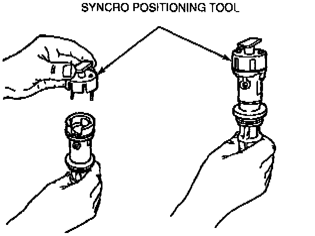
2. Align the synchronizer vane with the radial slot of the Syncro Positioning Tool T95T-12200-A.
3. Rotate the Syncro Positioning Tool on the synchronizer base until the tool's boss engages the base notch.
4. Dip gear end into ESE-M2C123-A oil to coat gear, thrust washer and lower bearing.
Synchronizer Assembly:
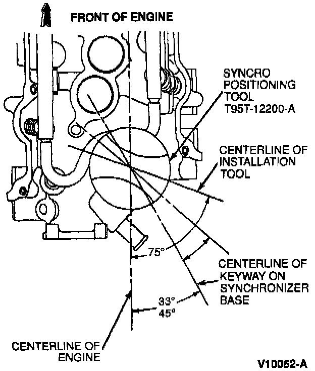
5. Insert the synchronizer assembly (with tool) into the block. The tool should be aimed approximately 75 degrees counterclockwise from the centerline of the engine.
6. Rotate the tool clockwise slightly to engage the oil pump intermediate shaft. Continue the downward motion, twisting the tool lightly until the synchronizer gear engages the camshaft gear.
7. With the synchronizer flange fully seated against the block, the tool should point rearward 33 to 45 degrees counterclockwise off engine centerline.
8. Install hold-down clamp and tighten to 18-29 Nm (13-21 lb ft).
CAUTION: If camshaft position sensor electrical connector is not positioned properly, DO NOT reposition the connector by rotating the synchronizer assembly. This will result in the fuel system being out of time with the engine, possibly causing engine damage. Remove the synchronizer assembly and repeat installation procedure, beginning with Step 1.
9. Remove Syncro Positioning Tool.
10. Install CMP sensor and retaining screws. Tighten screws to 1.5-4.0 Nm (14-35 lb in).
11. Connect fuel charging wiring to camshaft position sensor stator assembly.
12. Connect battery ground cable.
NOTE: When the battery has been disconnected and reconnected, some abnormal drive symptoms may occur while the powertrain control module (PCM) relearns its adaptive strategy. The vehicle may need to be driven 16 km (10 miles) or more to relearn the strategy.