Disassembly
1. Remove flywheel and engine rear plate.NOTE: Before starting disassembly, remove accessories and any emission control equipment which is not directly attached to engine.
2. Remove exhaust manifolds.
NOTE: When LH exhaust manifold is removed, note location of oil level indicator tube support bracket.
3. Remove following positive crankcase ventilation system components:
a. Front and rear crankcase ventilation tube.
b. Positive crankcase ventilation valve.
c. Crankcase ventilation grommet.
4. Remove water bypass tube.
5. Disconnect ignition wires from spark plugs.
NOTE: When removing an ignition wire from a spark plug, use Spark Plug Wire Remover. Grasp and twist boot back and forth on spark plug insulator to free boot. Use tool to pull boot from spark plug. Do not pull on ignition wire directly or it may become separated from the connector inside the boot.
6. Remove camshaft position sensor and camshaft position sensor housing.
7. Remove the upper intake manifold.
8. Remove intake manifold upper gasket.
9. Remove fuel injection supply manifold.
10. Remove crankshaft pulley and vibration damper. Use Crankshaft Damper Remover and Vibration Damper Remover Adapter to remove vibration damper.
11. Remove valve covers.
12. Remove lower intake manifold and intake manifold gaskets. Discard intake manifold gaskets and end seals.
CAUTION: Use care to prevent damage to machined surfaces or possible leakage may occur upon reassembly.
NOTE: Before attempting to remove lower intake manifold, break seal between intake manifold and cylinder block. Wedge a large prybar between intake manifold and cylinder block. Pry downward on prybar using lug on water pump as a leverage point.
13. Remove spark plugs.
14. Remove rocker arms and push rods.
NOTE: The location of each rocker arm, push rod and rocker arm seat should be noted. When engine is assembled each component should be installed in its original location.
15. Remove cylinder heads. Discard cylinder head retaining bolts. Remove and discard head gaskets.
16. Remove valve tappets, valve tappet guide plate and tappet guide plates and retainers.
NOTE:
- If valve tappets are stuck in bores due to excessive varnish or gum deposits, it may be necessary to use a magnet or a claw-type tool to aid removal. When using a remover tool, rotate valve tappet back and forth to loosen it from any gum or varnish that may have formed on valve tappet.
- The location of each valve tappet should be identified. When engine is assembled each valve tappet should be installed in its original location.
17. Remove oil bypass filter and engine oil cooler (if equipped).
18. Remove oil pan.
19. Remove oil pump screen cover and tube.
Discard oil pump inlet tube gasket.
20. Remove water pump and engine front cover as an assembly. Remove and discard engine front cover gasket.
NOTE: If necessary, water pump can be removed from engine front cover. Discard water pump housing gasket after removal.
21. Remove camshaft sprocket retaining bolt and washer from end of camshaft.
22. Remove distributor drive gear.
Distributor Gear:
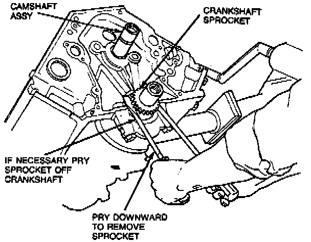
23. Remove camshaft sprocket, crankshaft sprocket, timing chain and timing chain vibration damper.
CAUTION: Use care to prevent damage to finished areas on crankshaft and crankshaft sprocket or component failure may occur.
NOTE: If crankshaft sprocket is difficult to remove, it can be loosened using two large prybars.
24. Remove engine balance shaft drive gear.
25. Remove camshaft thrust plate.
26. Remove camshaft. Use care to prevent damage to camshaft bearing surfaces.
27. If necessary, remove camshaft rear bearing cover from back of cylinder block.
28. Remove screws securing balance shaft thrust plate.
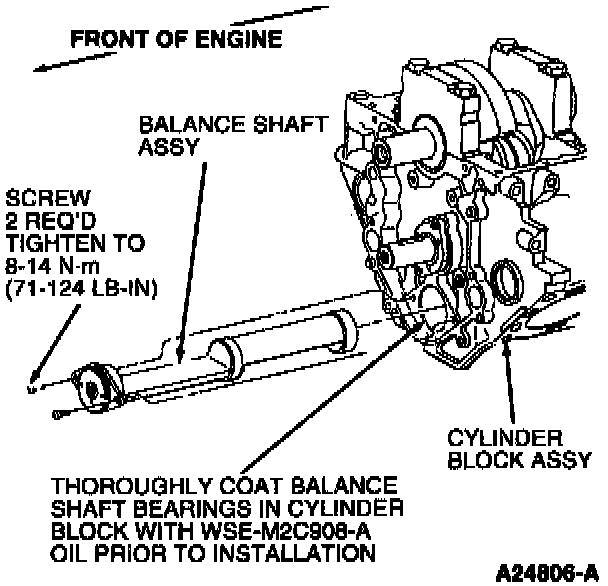
29. Remove balance shaft gear, balance shaft thrust plate and engine dynamic balance shaft.
CAUTION: Use care to prevent damage to bearing surface as possible bearing failure may occur.
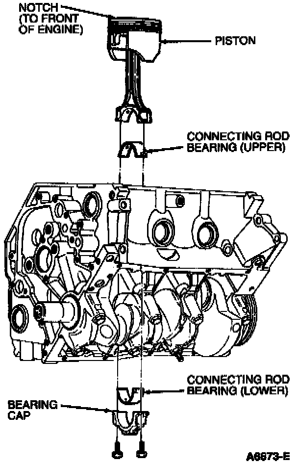
30. Remove connecting rod caps and install connecting rod guide tool over connecting rod bolt holes and push piston out through the top of the cylinder bore. Use care to prevent damage to crankshaft bearing surface(s).
CAUTION: Never cut into ring travel area in excess of 0.794mm (0.0325 inch) or damage to the cylinder block may occur.
NOTE: Before removing pistons, inspect top of cylinder bores. If necessary, remove ridge or carbon deposits from each cylinder using Rotunda Cylinder Ridge Reamer. Before ridge or deposits are removed, turn crankshaft until piston is at bottom of its stroke. Cover piston with a clean shop towel to collect cuttings. After cutting operation, turn crankshaft until piston is at top of its stroke and remove shop towel with cuttings.
31. Mark the location of each piston, connecting rod bearing and connecting rod cap. When engine is assembled each component should be installed in its original position.
32. Remove crankshaft main bearing caps and crankshaft.
33. Mark the location of crankshaft main bearings. When engine is assembled each crankshaft main bearing should be installed in its original position.
34. Clean and inspect pistons, connecting rods, crankshaft and cylinder block. Refinish or replace components as required.
NOTE: For cleaning purposes, oil gallery and cooling jacket plugs can be removed.