Disassembly and Assembly
1 Of 2:

2 Of 2:

Note: All fasteners are important because they can affect the performance of vital parts and systems. Incorrect installation of the fasteners can result in major repair expenses. They must be installed new with fasteners of the same part number if installation becomes necessary. Do not install a new part of lesser quality or substitute a design. Torque values must be used as specified during assembly to make sure these parts function correctly.
The body of the steering column (3C529) is made of magnesium die castings. The steering column is attached to a support that is an integral part of the instrument panel. The lower attachments of the steering column are through a bracket that bends during collapse. The upper attachments are through plastic shear modules that separate from the main casting during collapse. A clip and washer are attached to the shear modules to reduce steering column shake and to assist in installation of the steering column.
Special Tools:

Disassembly
WARNING: Always wear safety glasses when repairing an air bag supplemental restraint system (SRS) vehicle and when handling an air bag module. This will reduce the risk of injury in the event of an accidental deployment.
WARNING: Carry a live air bag module with the air bag and trim cover pointed away from your body. This will reduce the risk of injury in the event of an accidental deployment.
WARNING: Do not set a live air bag module down with the trim cover face down. This will reduce the risk of injury in the event of an accidental deployment.
/WARNING: After deployment, the air bag surface can contain deposits of sodium hydroxide, a product of the gas generant combustion that is irritating to the skin. Wash your hands with soap sad water afterwards.
WARNING: Never probe the connectors on the air bag module. Doing so can result in air bag deployment, which can result in personal injury.
WARNING: Air bag modules with discolored or damaged trim covers must be replaced, not repainted.
WARNING: Vehicle sensor orientation is critical for proper system operation. If a vehicle equipped with an air bag supplemental restraint system (SRS) is involved in a collision, inspect the sensor mounting bracket and wiring pigtail for deformation. Replace and properly position the sensor or any other damaged supplemental restraint system (SRS) components whether or not the air bag is deployed.
WARNING: To avoid accidental deployment and possible personal injury, the backup power supply must be depleted before repairing or replacing any front or side air bag supplemental restraint system (SRS) components and before servicing, replacing, adjusting or striking components near the front or side air bag sensors, such as doors, instrument panel, console, door latches, strikers, seats and hood latches.
The side air bag sensors are located at or near the base of the B-pillar.
To deplete the backup power supply energy, disconnect the battery ground cable and wait at least one minute. Be sure to disconnect auxiliary batteries and power supplies (if equipped).
1. Remove the steering column (3C529).

2. Remove the ignition switch (11572).
1. Remove the screws.
2. Remove the ignition switch.

3. CAUTION: Carefully note the position of the steering column lock gear, bearing and retainer prior to removal.
Remove the bearing retainer (3D681).

4. Remove the lock housing bearing (3E700).

5. Remove the lock gear (3E717).

6. Remove the sensor ring.
1. Remove the lower bearing spring.
2. Remove the sensor ring.

7. Remove the lower bearing tolerance ring from the shaft.

8. Remove the two tilt pivot screws.

9. WARNING: Steering column position spring is under tension and can come out with great force.
Remove the lock cylinder housing and shaft assembly from the actuator housing (3F723).
1. Pry up on the lock actuator lever (LH) (3D653) using a shop fabricated tool.
2. Remove the position spring (3D655).

10. Remove the turn indicator cancel cam.

11. Remove the snap ring.

12. Remove the upper bearing spring (3520).

13. Remove the bearing sleeve (3518).

14. Remove the lower bearing tolerance ring (3L539).
1. Slide the steering column shaft in toward the lock cylinder housing (3511).
2. Slide the steering column bearing tolerance ring from the steering column shaft and remove the shaft.

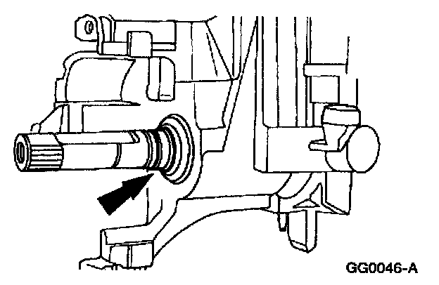
15. Using a suitable punch, remove the lower bearing (3517) from the lock cylinder housing.

16. Use a suitable punch to remove the bearing from the lock cylinder housing.

17. Remove the lower bearing and sleeve.

18. Remove the lower bearing retainer (3D681).
1. Remove the three bolts.
2. Remove the lower bearing retainer.

19. Remove the upper lock lever actuator (3E715) and the lower lock lever actuator.

20. Remove the ignition lock cylinder lockout lever.

21. Remove the lock actuator lever return spring.

22. Using a pin punch, remove the pin and lock actuator lever.

23. Using a pin punch, remove the pin and locking lever cam.

24. Note: Do not remove the tilt lock levers if not required.
Using a pin punch, remove the pin, tilt locking levers and springs.
Assembly
WARNING: Always wear safety glasses when repairing an air bag supplemental restraint system (SRS) vehicle and when handling an air bag module. This will reduce the risk of injury in the event of an accidental deployment.
WARNING: Carry a live air bag module with the air bag and trim cover pointed away from your body. This will reduce the risk of injury in the event of an accidental deployment.
WARNING: Do not set a live air bag module down with the trim cover face down. This will reduce the risk of injury in the event of an accidental deployment.
WARNING: After deployment, the air bag surface can contain deposits of sodium hydroxide, a product of the gas generant combustion that is irritating to the skin. Wash your hands with soap and water afterwards.
WARNING: Never probe the connectors on the air bag module. Doing so can result in air bag deployment, which can result in personal injury.
WARNING: Air bag modules with discolored or damaged trim covers must be replaced, not repainted.
WARNING: Vehicle sensor orientation is critical for proper system operation. If a vehicle equipped with an air bag supplemental restraint system (SRS) is involved in a collision, inspect the sensor mounting bracket and wiring pigtail for deformation. Replace and properly position the sensor or any other damaged supplemental restraint system (SRS) components whether or not the air bag is deployed.
WARNING: To avoid accidental deployment and possible personal injury, the backup power supply must be depleted before repairing or replacing any front or side air bag supplemental restraint system (SRS) components and before servicing, replacing, adjusting or striking components near the front or side air bag sensors, such as doors, instrument panel, console, door latches, strikers, seats and hood latches.
The side air bag sensors are located at or near the base of the B-pillar.
To deplete the backup power supply energy, disconnect the battery ground cable and wait at least one minute. Be sure to disconnect auxiliary batteries and power supplies (if equipped).
1. Install the locking lever cam and pin.

2. Install the lock actuator lever and pin.

3. install the lock actuator lever return spring.

4. Install the ignition lock cylinder lockout lever.

5. Note: The lock lever with two teeth is installed on the left-hand side.
If necessary, install the springs and lock levers.
1. Install the spring and lever on the left-hand side. Use a pin punch to hold the compressed spring in position.
2. Install the spring and lever on the right-hand side. Use the pivot pin to hold the compressed spring in position.
3. Tap the pin through the levers, pushing out the pin punch, until flush with the housing.

6. Install the lock lever actuators.
1. Lubricate the lock lever actuator with Ignition Lock Grease FOAZ-19584-A or equivalent meeting Ford specification ESA-M1C232-A.
2. Install the lock lever actuators.

7. Install the lower bearing retainer.
1. Position the lower bearing retainer.
2. Install the three bolts.


8. Note: The "UP" position of the bearing must be facing forward. Install the lower bearing and sleeve.


9. CAUTION: Install the steering column bearing so that the inner race is visible when installed.
Note: Use an appropriate bearing installer or socket.
Install the bearing in the lock cylinder housing.


10. CAUTION: Install the steering column bearing so that the inner race is visible when installed.
Note: Use an appropriate bearing installer or socket.
Install the bearing in the lock cylinder housing.

11. Position the shaft in the steering column lock cylinder housing.
^ Install the bearing tolerance ring on the steering column shaft.
12. Install the bearing sleeve.

13. Install the upper bearing spring.

14. Install the snap ring.

15. Install the tilt pivot screws loosely and position the actuator housing in a vise.
^ Lubricate pivot screws with Ignition Lock Grease FOAZ-19584-A or equivalent meeting Ford specification ESA-M1C232-A.

16. Place two nuts or spacers to hold the lock levers away from the actuator housing.

17. Note: Lubricate the lock cylinder housing pivot bushings with Ignition Dock Grease FOAZ-19584-A or equivalent meeting Ford specification ESA-M1C232-A.
Install the lock cylinder housing.
^ Position the lock cylinder housing and the shaft assembly on the actuator housing.
^ Make sure the upper and lower lock actuators are aligned.
^ Install and compress the steering column position spring.
^ Align the lock cylinder housing bushings with the pivot screws and tighten the screws.
^ Using a long thin screwdriver, remove the nuts installed under the lock levers.
18. Install the bearing tolerance ring.

19. Install the sensor ring.
1. Install the sensor ring.
2. Install the lower bearing spring.

20. Install the ignition switch. Align the ignition switch with the slot and index-mark on the actuator housing.
^ Install the screws.

21. Note: The narrow section of the keyhole in the lock should be in the one o'clock position.
Install the lock gear.
^ Use Ignition Lock Grease FOAZ-19584-A or equivalent meeting Ford specification ESA-M1C232-A to coat the lock gear.

22. Install the lock housing bearing.
^ The narrow section of the keyhole should be in the one o'clock position, with the tab inboard at the three o'clock position, and rotate it counterclockwise.
^ Lubricate the lock housing bearing with Ignition Lock Grease FOAZ-19584-A or equivalent meeting Ford specification ESA-M1C232-A.
23. Install the upper bearing retainer firmly to engage the four retention tabs into the lock housing.

24. Install the turn indicator cancel cam.
25. Install the steering column.