Initial Inspection and Diagnostic Overview
NOTE: The ignition switch must be cycled from OFF to RUN to enable the Switched System Power (SSP) feature.1. Verify the customer concern by operating the system.
2. Visually inspect for obvious signs of mechanical or electrical damage.
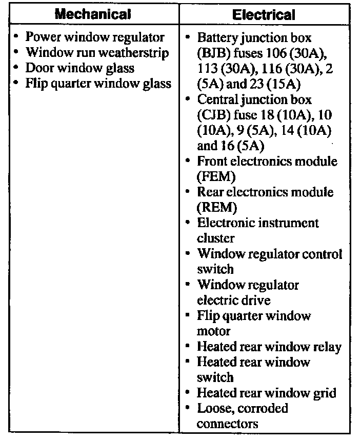
VISUAL INSPECTION CHART
3. If an obvious cause for an observed or reported concern is found, correct the cause (if possible) before proceeding to the next step.
4. If the scan tool does not power up, refer to the scan tool manual.
5. Carry out the DATA LINK DIAGNOSTIC TEST. If the scan tool responds with:
^ CKT 914, CKT 915 or CKT7O - ALL ECUS NO RESP/NOT EQUIP, refer to Module Communication Networks (Information Bus).
^ NO RESP/NOT EQUIP for the Front Electronics Module (FEM), go to Pinpoint Test A. Test A: No Communication With the Front Electronic Module
^ NO RESP/NOT EQUIP for the Rear Electronics Module (REM), go to Pinpoint Test B. Test B: No Communication With the Rear Electronic Module
^ NO RESP/NOT EQUIP for the Electronic Instrument Cluster (IC), go to Pinpoint Test C. Test C: No Communication With the Instrument Cluster
^ System passed, retrieve and record the continuous Diagnostic Trouble Codes (DTCs), erase the continuous DTCs and carry out self test diagnostics for the FEM, REM and instrument cluster modules.
6. If the FEM DTCs retrieved are related to the concern, go to the FEM Diagnostic Trouble Code (DTC) Index. FEM Diagnostic Trouble Code (DTC) Index
7. If the REM DTCs retrieved are related to the concern, go to the REM Diagnostic Trouble Code (DTC) Index. REM Diagnostic Trouble Code (DTC) Index
8. If the instrument cluster DTCs retrieved are related to the concern, go to the Instrument Cluster Diagnostic Trouble Code (DTC) Index. Instrument Cluster Diagnostic Trouble Code (DTC) Index
9. If no DTCs related to the concern are retrieved, proceed to the Symptom Chart to continue diagnostics. Symptom Related Diagnostic Procedures