Vehicles Built Before 6/2003
Steering Column-Vehicles Built Before 6/2003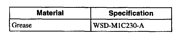
Material
Disassembly
All vehicles
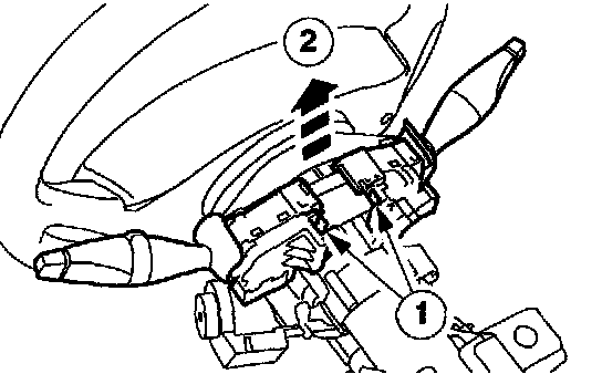
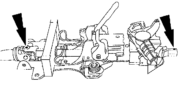
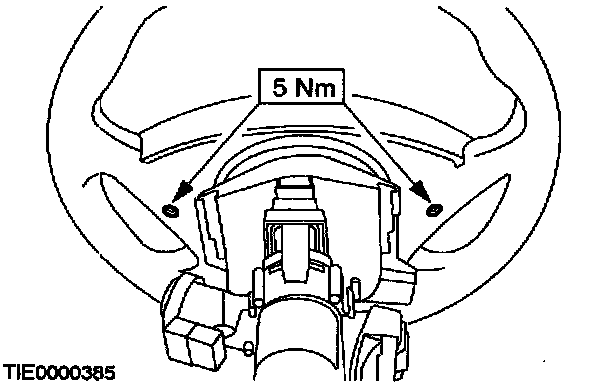
1. Remove the two multifunction switches.
1 Depress the retaining tangs.
2 Lift the switches upwards.

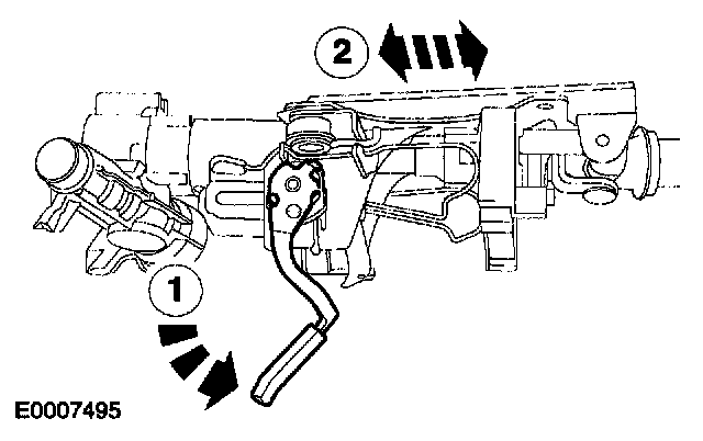
2. Detach the driver air bag module from the steering wheel.
3. Remove the driver air bag module.
^ Release the three clips.
^ Disconnect the air bag module electrical connector.
4. Remove the passive anti-theft system (PATS) transceiver.

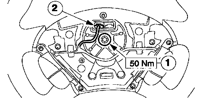
5. Remove the steering wheel.
1 Disconnect the speed control electrical connector (if equipped).
2 Remove the steering wheel retaining bolt.
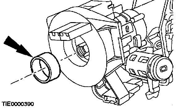
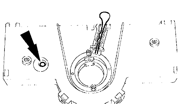
6. Remove the tolerance ring.
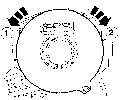
7. NOTE: Make sure the clockspring is not allowed to rotate. Secure in the central position with a piece of suitable tape.
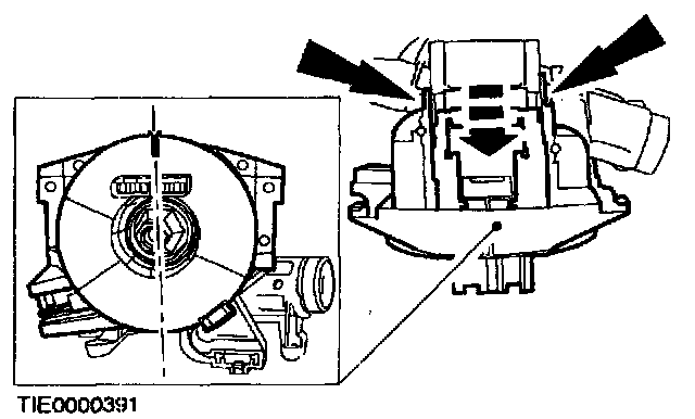
Remove the clockspring.
^ Using a thin bladed screwdriver, release the two retaining clips.
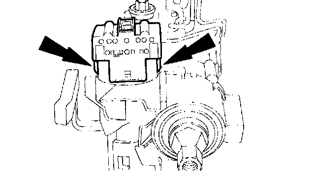
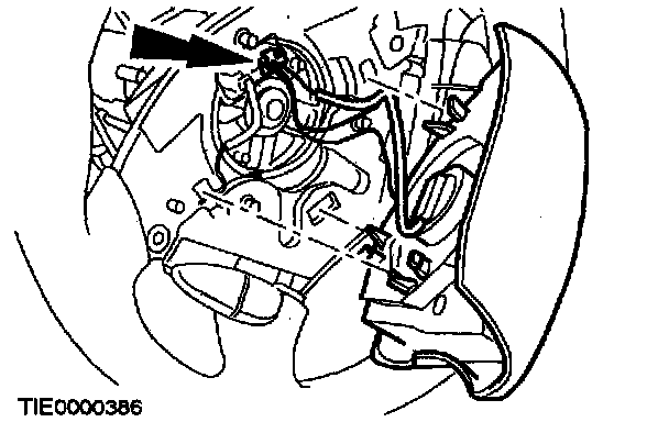
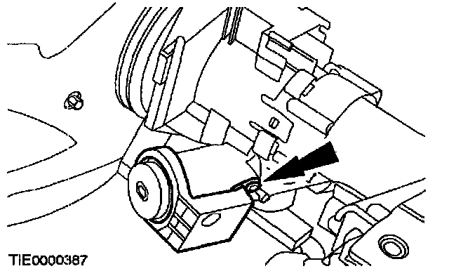
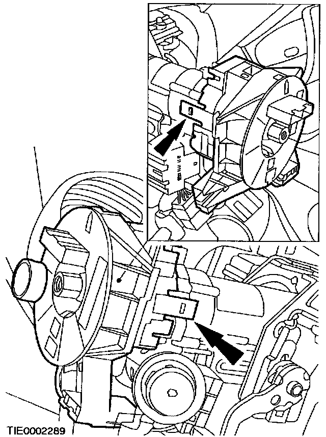
8. Remove the ignition switch.
^ Release the clips.
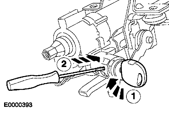
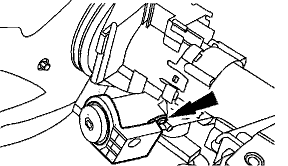
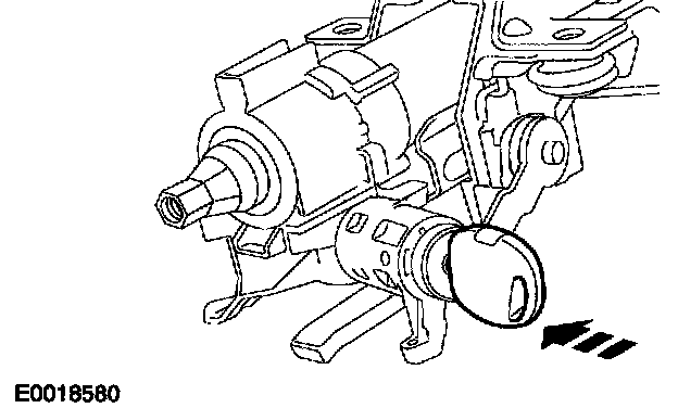
9. Remove the ignition switch lock cylinder.
1 Insert and turn the ignition key to position I (Accessory).
2 Using a thin bladed screwdriver, depress the detent.
^ Remove the ignition switch lock cylinder.
Vehicles with stability assist
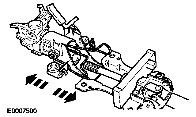
10. Fully extend the steering column
1 Release the locking lever.
2 Fully extend the steering column.
11. NOTE: The steering column two halves must be marked before separating.
Mark the two halves of the steering column.
All vehicles
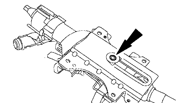
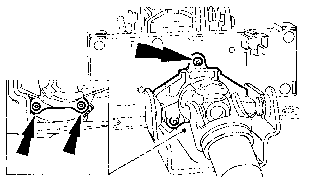
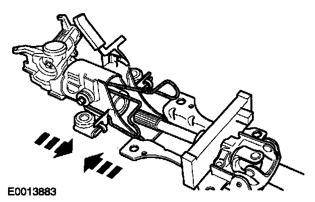
12. Remove the Allen bolt.
13. Separate the steering column two halves.
Vehicles with stability assist

14. Remove the steering wheel rotation sensor clamp.
1 Remove the screws
2 Using a thin bladed screwdriver, depress the locking tangs and remove the steering wheel rotation sensor clamp.
15. Remove the steering wheel rotation sensor retaining screws.

16. Remove the steering wheel rotation sensor.
Assembly
Vehicles with stability assist
1. WARNING: Do not install a new steering wheel rotation sensor, if the locking pin has been removed. Failure to follow this instruction may result in personal injury.
WARNING: Before fitting the steering wheel rotation sensor, make sure the rotor is in the correct position. Failure to follow this instruction may result in personal injury.
Check that the alignment indicator is in the correct position.
2. WARNING: Make sure the steering wheel rotation sensor retaining screws are not over tightened. Failure to follow this instruction may result in personal injury.
Install the steering wheel rotation sensor.
3. WARNING: Make sure the steering wheel rotation sensor retaining clamp screws are not over tightened. Failure to follow this instruction may result in personal injury.
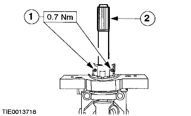
Install the steering wheel rotation sensor clamp.
1 Install the screws.
2 Apply grease to Ford specification, to the steering column splines.
All vehicles
4. NOTE: Make sure the steering column shafts are aligned correctly.
Connect the steering column two halves.
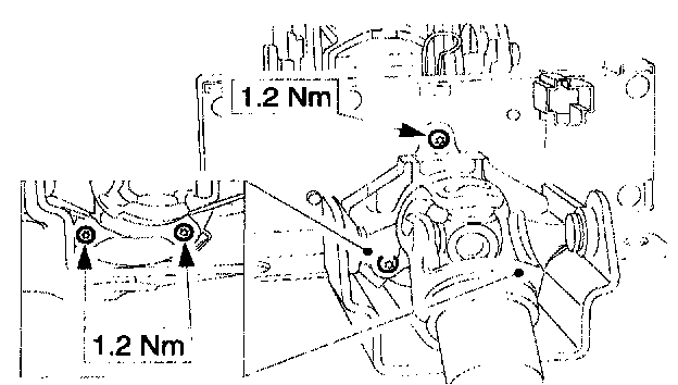
5. WARNING: Make sure the breakaway capsules are located in-the holes in the bracket. Failure to follow this instruction may result in personal injury.
WARNING: Make sure the bolt is not over tightened. Failure to follow this instruction may result in personal injury.

Install the steering column bolt.
1 Align the breakaway capsules.
2 Tighten the steering column bolt.
6. Install the ignition switch lock cylinder.
7. Install the ignition switch.
8. Install the passive anti-theft system (PATS) transceiver.
9. WARNING: Make sure the clockspring is centralized before installing. Failure to follow this instruction may result in personal injury.
Centralize the clockspring.
1 Turn the clockspring in a COUNTERCLOCKWISE direction until a resistance is felt (approximately 2.5 turns from the central position).
2 Turn the clockspring CLOCKWISE 2.5 turns until the arrow marked on the center of the sliding contact aligns with the raised "V" section at the 12 o'clock position on the outer cover of the clockspring. The clockspring is now centralized.
10. CAUTION: Make sure the spacing collar is correctly located. Do not assemble if the spacing collar is missing.
Install the air bag sliding contact.
^ Make sure both the retaining tangs lock into position on the steering column.

11. Install the multifunction switches.
12. Install the steering wheel.
1 Install the bolt.
2 Connect the speed control electrical connector (if equipped).
13. Install the driver air bag module.
^ Connect the air bag module electrical connector.
14. Attach the driver air bag module to the steering wheel.