Deactivate
SUPPLEMENTAL RESTRAINT SYSTEM (SRS) DEACTIVATION AND REACTIVATIONSpecial Tool(s):

SPECIAL TOOL(S)
Deactivation
WARNING:
- Always wear safety glasses when repairing an air bag supplemental restraint system (SRS) vehicle and when handling an air bag module. This will reduce the risk of injury in the event of an accidental deployment.
- Carry a live air bag module with the air bag and trim cover pointed away from your body. This will reduce the risk of injury in the event of an accidental deployment.
- Do not set a live air bag module down with the trim cover face down. This will reduce the risk of injury in the event of an accidental deployment.
- After deployment, the air bag surface can contain deposits of sodium hydroxide, a product of the gas generant combustion that is irritating to the skin. Wash your hands with soap and water afterwards.
- Never probe the connectors on the air bag module. doing so can result in air bag deployment, which can result in personal injury.
- The safety belt pretensioner is a pyrotechnic device. Always wear safety glasses when repairing an air bag equipped vehicle and when handling a safety belt buckle pretensioner or safety belt retractor pretensioner. Never probe a pretensioner electrical connector. Doing so could result in pretensioner or air bag deployment and could result in personal injury.
- Never probe the connectors on the air bag module. Doing so can result in side air curtain deployment.
- Vehicle sensor orientation is critical for proper system operation. If a vehicle equipped with an air bag supplemental restraint system (SRS) is involved in a collision, inspect the sensor mounting bracket and wiring pigtail for deformation. Replace and properly position the sensor or any other damaged supplemental restraint system (SRS) components whether or not the air bag is deployed.
- The restraint system diagnostic tool is for restraint system service only. Remove from vehicle prior to road use. Failure to remove could result in injury and possible violation of vehicle safety standards.
NOTE:
- If a seat equipped with a seat mounted side air bag and/or a safety belt pretensioner (if equipped) system is being serviced, the air bag system must be deactivated.
- Restraint system diagnostic tools MUST be installed under the seats in the seat side air bag (if equipped) and safety belt pretensioner (if equipped) to floor connectors.
- Diagnostics or repairs are not to be carried out on a seat equipped with a seat side air bag with the seat in the vehicle. Prior to attempting to diagnose or repair a seat concern when equipped with a seat side air bag, the seat must be removed from the vehicle and the restraint system diagnostic tools must be installed in the seat side air bag electrical connectors. The restraint system diagnostic tools must be removed prior to operating the vehicle over the road.
- After diagnosing or repairing an SRS, the restraint system diagnostic tools must be removed before operating the vehicle over the road.
- After diagnosing or repairing a seat system, the restraint system diagnostic tools must be removed before operating the vehicle over the road.
- The SRS must be fully operational and free of faults before releasing the vehicle to the customer.
1. WARNING: To avoid accidental deployment and possible personal injury, the backup power supply must be depleted before repairing or replacing any front or side air bag supplemental restraint system (SRS) components and before servicing, replacing, adjusting or striking components near the front or side air bag sensors, such as doors, instrument panel, console, door latches, strikers, seats and hood latches.
The side impact sensors are attached to the rocker panels, near the seats.
To deplete the backup power supply energy, disconnect the battery ground cable and wait at least one minute. Be sure to disconnect auxiliary batteries and power supplies (if equipped).
Disconnect the battery ground cable and wait at least one minute.

2. Remove the two steering wheel back cover plugs (one shown).

3. Remove the two driver air bag module retaining bolts (one shown).
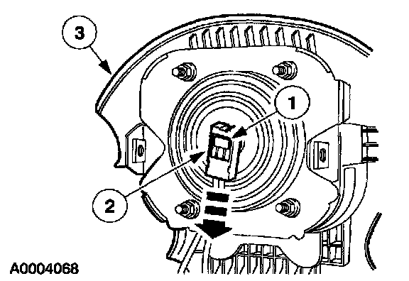
4. Disconnect and remove the driver air bag module.
1 Slide and disengage the driver air bag electrical connector locking clip.
2 Depress the locking tabs and disconnect the driver air bag module electrical connector.
3 Remove the driver air bag module.

5. Attach the restraint system diagnostic tool to the clockspring electrical connector at the top of the steering column.
6. Remove the glove compartment and door.

7. NOTE: The passenger air bag electrical connector is not visible due to its mounting position in the instrument panel.
The illustration shows the vicinity in which the passenger air bag electrical connector is located.
Reach into the glove box opening toward the center of the instrument panel, above the cross-car beam and locate the passenger air bag module electrical connector.
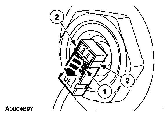
8. NOTE: The passenger air bag module is shown with instrument panel removed for clarity. This is a blind operation due to the passenger air bag module electrical connector mounting location.
Disconnect the passenger air bag module electrical connector (this is a blind operation).
1 Slide and disengage the passenger air bag module electrical connector locking clip.
2 Push in on the two release tabs and disconnect the passenger air bag module electrical connector.

9. Attach the restraint system diagnostic tool to the vehicle harness side of the passenger air bag electrical connector.
10. Connect the battery ground cable.
11. Move and tilt the front seats to their highest and most forward position.
12. WARNING: To avoid accidental deployment and possible personal injury, the backup power supply must be depleted before repairing or replacing any front or side air bag supplemental restraint system (SRS) components and before servicing, replacing, adjusting or striking components near the front or side air bag sensors, such as doors, instrument panel, console, door latches, strikers, seats and hood latches.
The side impact sensors are attached to the rocker panels, near the seats.
To deplete the backup power supply energy, disconnect the battery ground cable and wait at least one minute. Be sure to disconnect auxiliary batteries and power supplies (if equipped).
Disconnect the battery ground cable and wait at least one minute.

13. From under the passenger seat, release the tab and disconnect the passenger seat side air bag electrical connector.

14. Attach the restraint system diagnostic tool to the passenger seat side air bag floor electrical connector.

15. Remove the passenger side door scuff plate and weather-stripping.

16. Remove the safety belt from the passenger seat guide.
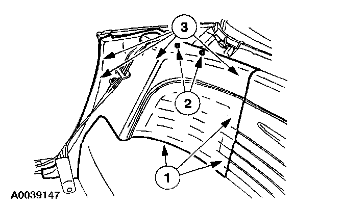
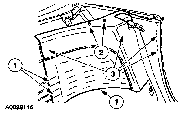
17. Separate the passenger side rear trim panel.
1 Pull out to release the retainers and remove the speaker grille.
2 Remove the snap screws.
3 Pull out to release the retaining clips and separate the passenger side rear trim panel.
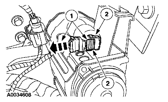
18. Disconnect the passenger safety belt retractor pretensioner electrical connector.
1 Slide and disengage the passenger safety belt retractor electrical connector locking clip.
2 NOTE: Pulling the safety belt webbing out of the retractor, can aid in releasing the lower safety belt retractor pretensioner electrical connector retaining tab.
Pushing in on the two release tabs, disconnect the passenger safety belt retractor electrical connector.

19. Attach the restraint system diagnostic tool to the passenger safety belt retractor pretensioner electrical connector.

20. From under the driver seat, release the tab and disconnect the driver seat side air bag electrical connector.

21. Attach the restraint system diagnostic tool to the driver seat side air bag floor electrical connector.
22. Remove the driver side door scuff plate and weather-stripping.

23. Remove the safety belt from the driver seat guide.
24. Separate the driver side rear trim panel.
1 Pull out to release the retainers and remove the speaker grille.
2 Remove the snap screws.
3 Pull out to release the retaining clips and separate the driver side rear trim panel.

25. Disconnect the driver safety belt retractor pretensioner electrical connector.
1 Slide and disengage the driver safety belt retractor electrical connector locking clip.
2 NOTE: Pulling the safety belt webbing out of the retractor, can aid in releasing the lower safety belt retractor pretensioner electrical connector retaining tab.
Pushing in on the two release tabs, disconnect the driver safety belt retractor electrical connector.

26. Attach the restraint system diagnostic tool to the driver safety belt retractor pretensioner electrical connector.
27. Connect the battery ground cable.
28. With the restraint system diagnostic tools installed at all deployable devices, prove out the supplemental restraint system (SRS). Prove Out Procedure
29. Disconnect the battery ground cable and wait at least one minute.