Steering Column
Steering Column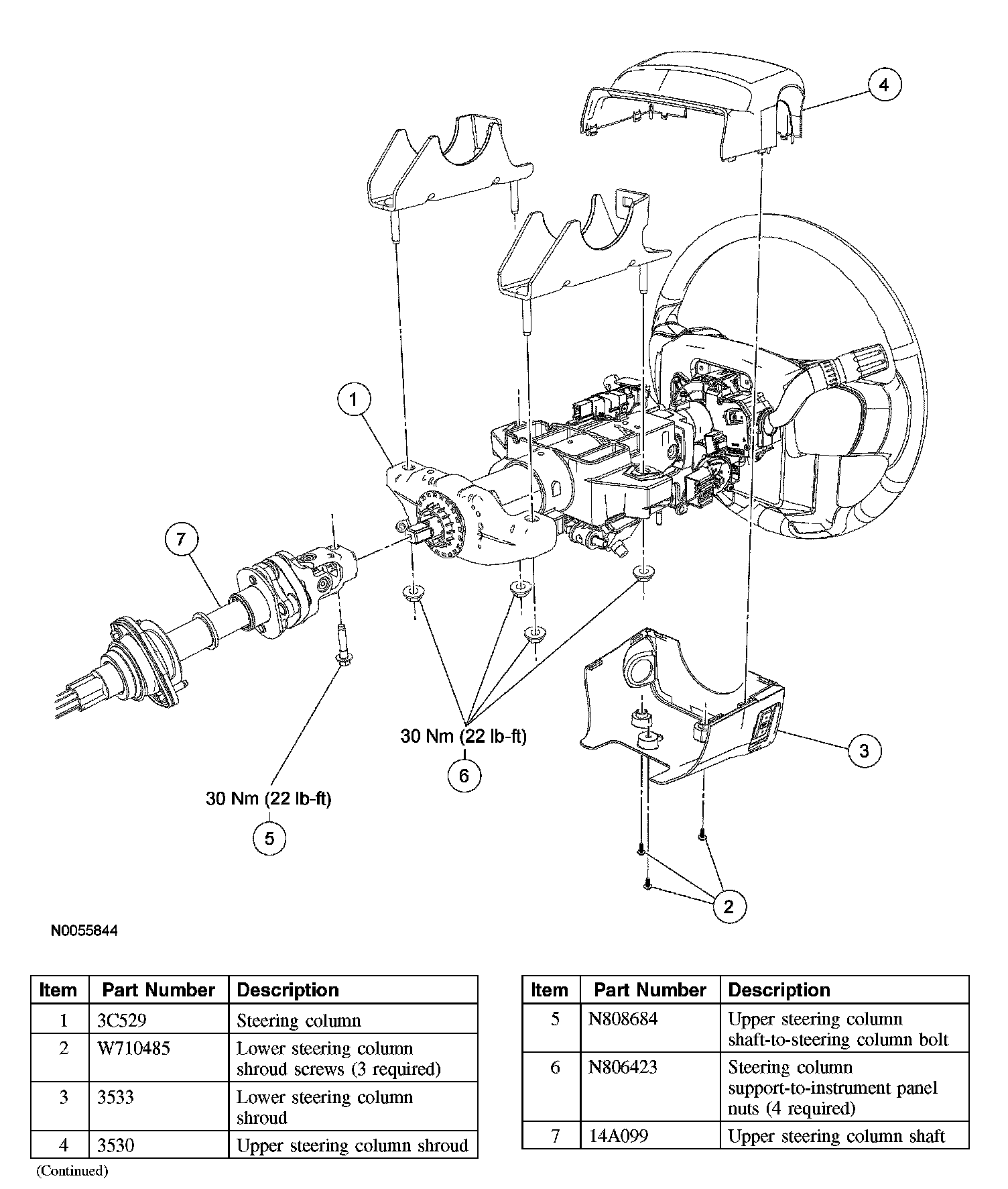
Removal and Installation
All vehicles
1. Place the steering wheel in the straight-ahead position and turn the ignition switch to the OFF position.
^ Remove the key.
2. Depower the supplemental restraint system (SRS).
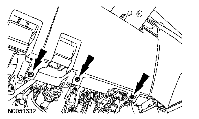
3. Remove the lower steering column opening cover.
^ Remove the 3 screws and pull out to release the top retaining clips and remove the lower steering column opening cover.
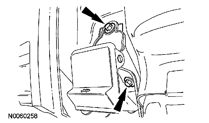
4. Remove the 2 bolts and position aside the hood release handle.
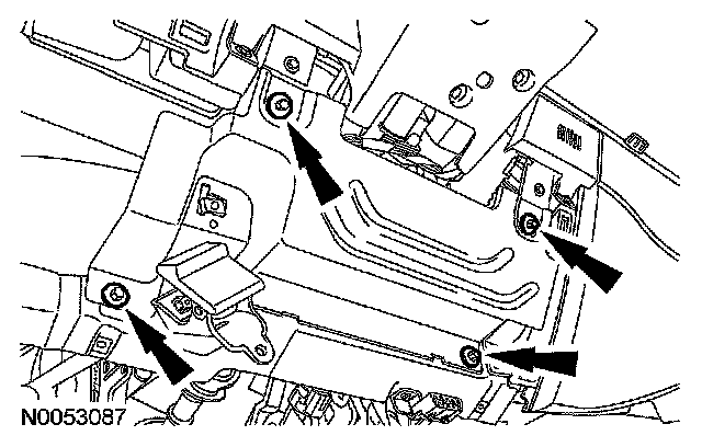
5. Remove the 4 bolts and the steering column reinforcement cover.
^ To install, tighten to 9 Nm (80 lb-in).
Vehicles with column shift
6. Release the tabs and slide the gear selector cover away from the steering column shrouds.
All vehicles
7. Remove the 3 screws and the upper and lower steering column shrouds.
^ If equipped, disconnect the power tilt electrical connector switch from the lower shroud.
^ To install, tighten to 2 Nm (18 lb-in).
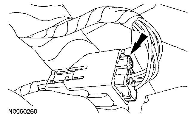
8. Disconnect the following electrical connectors.
^ Clockspring
^ PATS transceiver
^ Ignition switch
^ Multi-function switch
^ Steering angle rotational sensor
^ Key release interlock actuator (if equipped).
Vehicles with power tilt
9. Disconnect the power tilt motor electrical connector.
Vehicles with column shift
10. Detach the shift cable from the steering column and the bracket.
11. Disconnect the overdrive cancel switch and brake shift interlock solenoid jumper harness connector located at the top of the lower steering column support bracket.
All vehicles
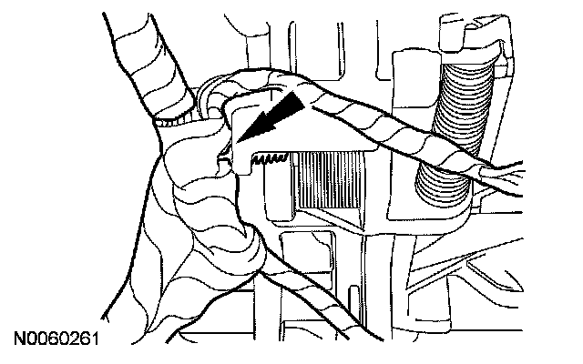
12. Detach the wiring harness retainer from the steering column and position the wiring harness aside.
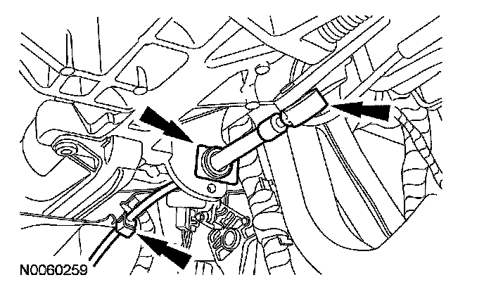
13. CAUTION: Do not allow the steering column shaft to rotate while the intermediate shaft is disconnected or damage to the clockspring can result. If there is evidence that the shaft has rotated, the clockspring must be removed and recentered.
Remove the bolt and detach the upper steering column shaft from the steering column.
^ Discard the bolt.
^ To install, tighten to 30 Nm (22 lb-ft).
14. Remove the 4 nuts and the steering column.
^ Discard the nuts.
^ To install, tighten to 30 Nm (22 lb-ft).
15. CAUTION: Make sure that the steering column support is flush with the instrument panel before tightening the nuts.
CAUTION: Make sure the electrical wiring harness is routed correctly and secured to the steering column or damage to the wires and/or connectors can occur.
To install, reverse the removal procedure.
Vehicles with power tilt
16. Reset the steering column soft stops.