Overhaul
Steering ColumnDisassembly
All vehicles
WARNING: To avoid the risk of serious personal injury, read and follow all warnings, notes and instructions in the deactivation procedure.
CAUTION: Do not allow the steering wheel to rotate while the intermediate shaft is disconnected or damage to the clockspring can result. If there is evidence that the shaft has rotated, the clockspring must be removed and recentered. For additional information, refer to Air Bag Systems.
1. Remove the steering column.
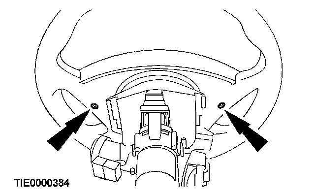
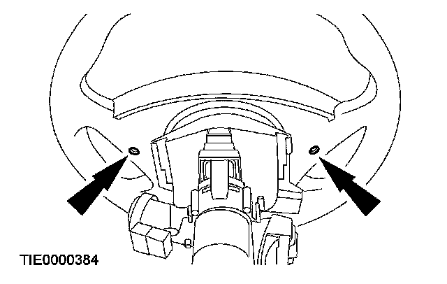
2. Remove the 2 driver air bag module screws.
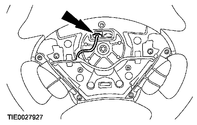
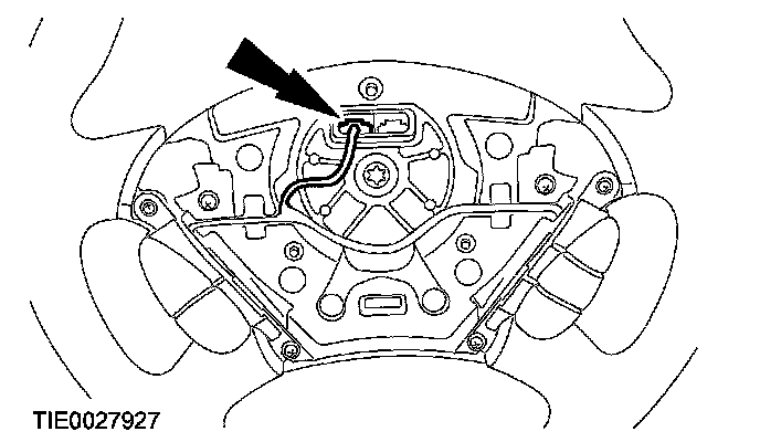
3. Disengage the clips, disconnect the electrical connector and remove the driver air bag module.
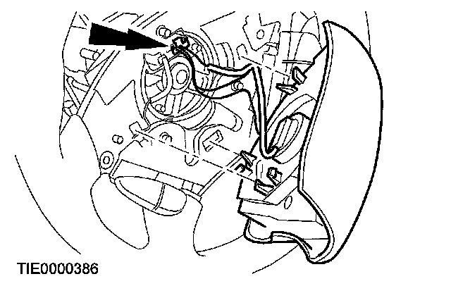
4. If equipped, disconnect the speed control electrical connector.
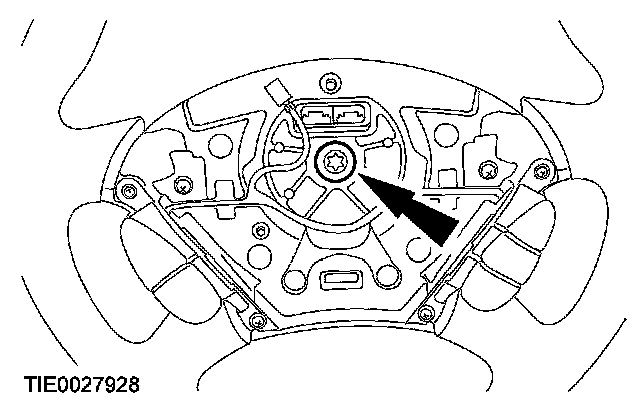
5. Remove the steering wheel bolt and the steering wheel.
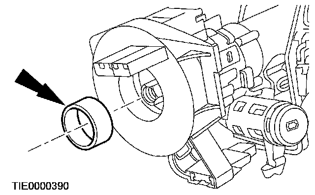
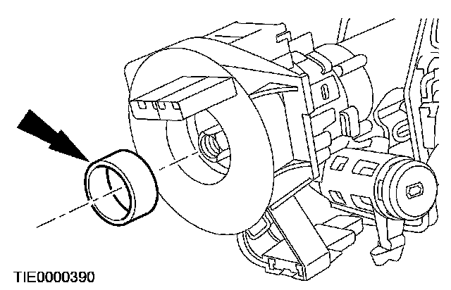
6. Remove the spacing collar.
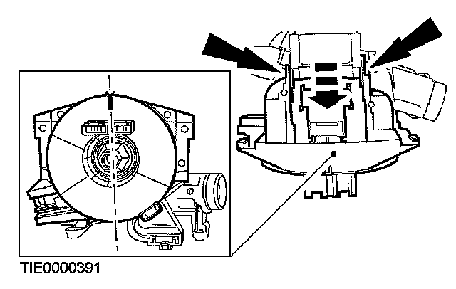
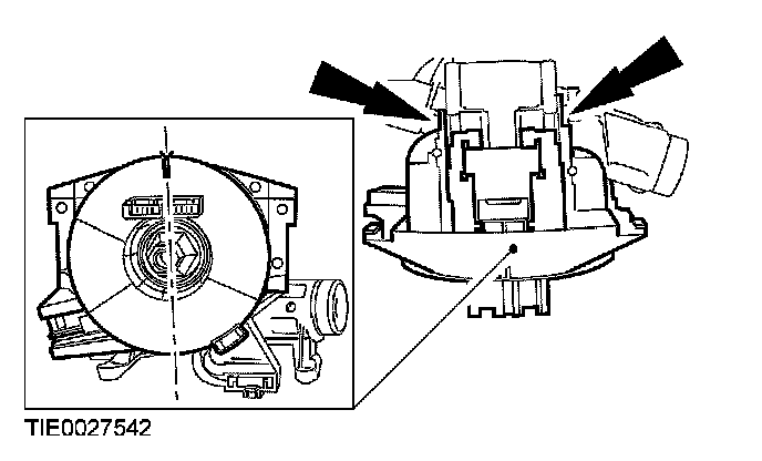
7. CAUTION: Make sure the clockspring is not allowed to rotate. Secure in the central position with a piece of suitable tape.
Using a suitable tool, release the retaining clips and remove the clockspring.
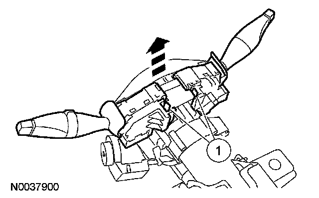
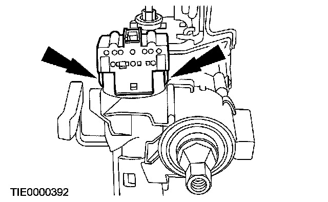
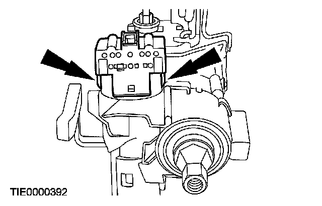
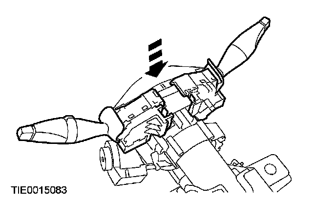
8. Remove the steering column multi-function switches.
1. Press the retaining tabs.
^ Lift the switches upward.
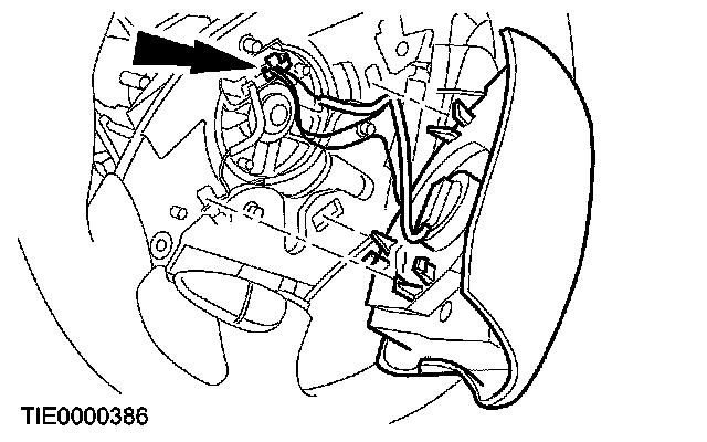
9. Remove the passive anti-theft system (PATS) transceiver.
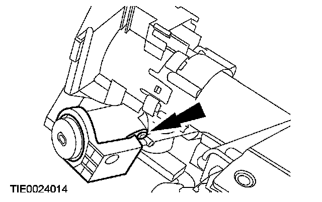
10. Release the locking tabs and remove the ignition switch.
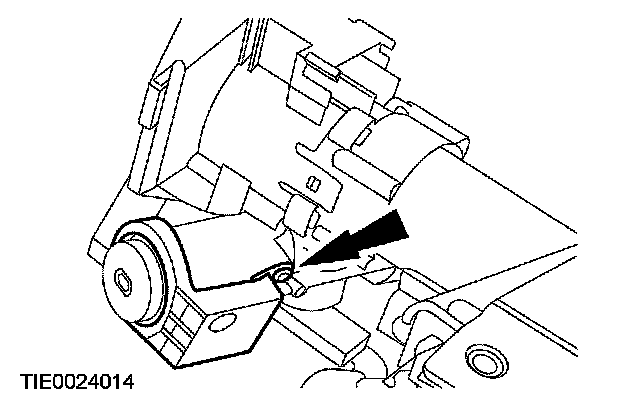
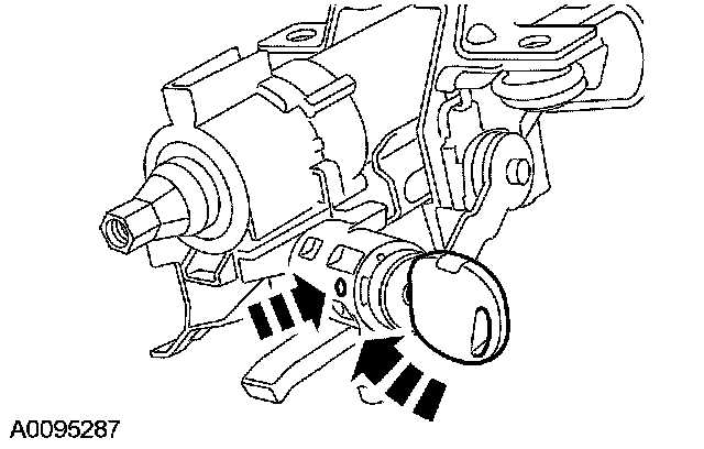
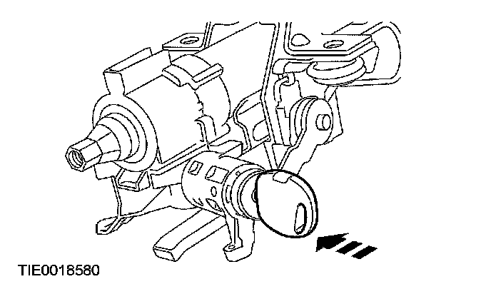
11. NOTE: Make sure to maintain synchronous positioning between the ignition lock cylinder and the ignition switch while the ignition lock cylinder is removed.
Remove the ignition switch lock cylinder.
^ Insert and turn the ignition key to the ON position.
^ Using a suitable tool, press the detent and pull the ignition lock cylinder out.
Vehicles with telescoping column
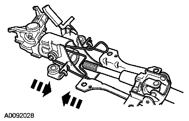
12. Release the locking lever and fully extend the steering column.

13. NOTE: The 2 halves of the steering column must be marked before separating to aid assembly.
Mark the 2 halves of the steering column.
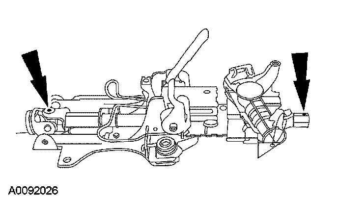
14. Remove the steering column sliding bolt.

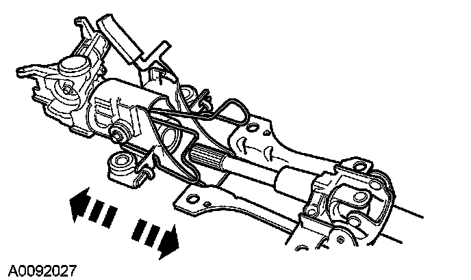
15. Separate the 2 halves of the steering column.
Assembly
Vehicles with telescoping column
1. NOTE: Make sure the steering column shafts are aligned correctly.
Connect the 2 halves of the steering column.
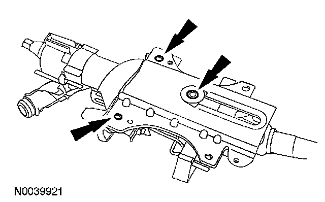
2. WARNING: Make sure the breakaway capsules are located in the holes in the bracket. Failure to follow these instructions may result in personal injury.
WARNING: Make sure the bolt is not over tightened. Failure to follow these instructions may result in personal injury.
Align the breakaway capsules and install the steering column sliding bolt.
^ Tighten to 5 Nm (44 inch lbs.).
All vehicles
3. CAUTION: Make sure to maintain synchronous positioning between the ignition lock cylinder and the ignition switch while installing them.
Install the ignition lock cylinder.
^ Rotate the ignition key.
4. Install the ignition switch.
5. Install the PATS transceiver.
6. NOTE: Make sure both the retaining tabs lock into position on the steering column.
Install the clockspring.
7. CAUTION: Make sure the spacing collar is correctly located. Do not assemble if the spacing collar is missing. Failure to do so will damage the clockspring.
Install the spacing collar.
8. Install the steering column LH and RH multi-function switches.
CAUTION: Do not allow the steering wheel to rotate while the intermediate shaft is disconnected or damage to the clockspring can result. If there is evidence that the shaft has rotated, the clockspring must be removed and recentered.
For additional information, refer to Air Bag Systems.
9. Remove the tape from the clockspring.
10. Position the steering wheel and install the bolt.
^ Tighten to 48 Nm (35 ft. lbs.).
11. If equipped, connect the speed control electrical connector.
12. Connect the driver air bag module electrical connector.
13. Position the driver air bag module and install the 2 screws.
^ Tighten to 5 Nm (44 inch lbs.).
14. Install the steering column.