Principles of Operation
PRINCIPLES OF OPERATIONMedium Speed Controller Area Network (MS-CAN)
This vehicle utilizes a communication system called a medium.speed controller area network (MS-CAN). When diagnosing the memory seat or climate controlled seat, use a Vehicle Communication Module (VCM) and Integrated Diagnostic System (IDS) software with appropriate hardware, or equivalent scan tool with the latest software update with the capability of communicating over the MS-CAN bus.
Driver and Passenger Power Seats Without Memory
The 10-way seat control feature (MKZ passenger seat only) moves the seat in 10 possible directions: the seat can be moved forward or backward and the front and back of the cushion can be moved up and down independently. The backrest of the seat can be moved forward and backward, and the lumbar can be moved IN and OUT. All 10 positions are controlled by one switch. The power seat feature operates independent of the ignition switch position. The 6.way power seat feature moves the seat in 6 possible directions: the seat can be moved forward or backward and the front and back of the cushion can be moved up and down independently. The power seat feature operates independent of the ignition switch position.
The power seat motors are hardwired to the seat control switch. The circuits are normally at ground through the seat control switch. An individual circuit is switched to power when a specific adjustment position is selected.
Power Driver Seat With Memory
The memory driver seat feature allows the driver to program a personalized seat position that can be recalled using the memory switch or a remote keyless entry (RKE) transmitter. There are 2 memory settings possible. The outside rear view mirror positions and the power adjustable pedals (if equipped) are also stored and recalled with the power driver seat positions.
The driver power seat is controlled by the driver seat module (DSM), if equipped. A new DSM must be configured after installation. Refer to Information Bus (Module Communications Network).
The driver seat control switch provides voltage to the DSM when activated. The NEUTRAL position of each driver seat control switch position is a ground state through the seat control switch contacts. A voltage input causes the DSM to power the appropriate motor until the input is removed. Ground is the normal state of the motor circuits through the DSM and is not switched to control the motors. The DSM internally switches the appropriate circuit from ground to power for operating the motors.
As the seat is adjusted, the DSM constantly monitors the motor position sensors to record the current seat position. The DSM will remove power from the motor upon termination of the seat control switch input or if the DSM does not see movement from the motor by monitoring the position sensor. The DSM must be calibrated to the driver seat track for correct memory seat operation. Refer to Seat Calibration. Once the DSM is calibrated to the seat track, it will only allow movement within the calibrated range.
The DSM communicates diagnostic trouble code (DTC) and other information using the MS-CAN communication bus. It should be noted for diagnostics that because CAN bus communication is more robust and reliable than other methods, it may be possible to have limited module communication with one of the CAN bus circuits disconnected or shorted to ground. Refer to Information Bus (Module Communications Network) for additional information concerning MS-CAN bus communication.
Programming Memory Seat Positions
- A power driver seat position can be stored at any time. The driver must move the seat to the desired position using the driver seat control switch. The driver must then depress the memory SET switch which activates the memory SET switch light emitting diode (LED). Within 5 seconds (before the LED goes out), the driver must select a memory position. Memory 1 is selected by depressing memory switch 1. Memory 2 is selected by depressing memory switch 2.
- If no memory switch input is received within the 5-second time limit, the operation is aborted and the memory SET switch LED is turned OFF. If one of the following inputs is received during the 5-second programming limit, the operation is aborted and the memory SET switch LED is turned OFF:
- Power driver seat control switch
- Memory SET switch
- Power adjustable pedal switch
Recalling a Stored Memory Seat Position
NOTE: A memory recall can be initiated only if the vehicle is in PARK or NEUTRAL gear and the ignition switch is not in START. A memory recall in progress will not be affected by moving the ignition switch to START or by moving the gearshift lever out of PARK or NEUTRAL. Once the driver has stored the driver seat position, the driver can recall the setting by depressing the corresponding memory switch or by using a programmed remote entry transmitter.
The driver can recall the desired driver seat position by depressing one of the memory recall switches. Depressing memory switch 1 will initiate a recall of the power driver seat position stored in Memory 1. Depressing memory switch 2 will initiate a recall of the power driver seat position stored in Memory 2.
A remote entry transmitter can be used to recall previously set memory positions. The transmitter that has been assigned with personality 1 is capable of recalling memory position 1 only. Similarly, the personality 2 transmitter can recall only memory position 2.
Memory recall occurs when the unlock switch is depressed on the remote entry transmitter. The second depression of the unlock switch, which unlocks passenger doors, does not initiate a memory recall.
A memory recall in progress does not prohibit the initiation of another memory recall; the most recently requested memory recall will be executed. Memory positions that have not been programmed will not initiate any motion for the power driver seat, power memory rear view mirrors or adjustable pedals.
Easy Exit/Easy Entry
The easy exit function moves the seat backwards about 2 inches when the ignition key is removed from the ignition switch. The DSM receives a key out command over the MS-CAN communication network and powers the driver seat rearward. This function will not operate if the seat is less than the travel distance to the end of the track or the function has been deactivated. The DSM will also cancel this operation if a valid input command is received, such as the seat control switch or memory recall request.
The DSM will record the current seat position before powering the seat for an easy exit function. This recorded position will be used to return the seat to this position on the easy entry operation. During easy entry operation, the seat is returned to the position previous to the easy exit operation. Easy entry operation will be cancelled if a valid input command is received by the DSM.
The easy exit/easy entry feature can be activated or deactivated using a scan tool or via the message center. Refer to Information Bus (Module Communications Network) or the owner's literature.
Heated Seats
Vehicles equipped with front heated seats are equipped with a single.heated seat module to control both front heated seats. The heated seat module is located on the passenger seat track. The electronic automatic temperature control (EATC) module includes both driver and passenger heated seat control buttons and indicators. The heated seat system will function independently of the vehicle's climate control system. A momentary ground signal is transmitted to the heated seat module when a heated seat switch button on the EATC module is depressed and ignition switched voltage is supplied. Upon receiving each control signal to an input circuit, the heated seat module will decrease one setting (the sequence is HI, LOW, OFF, HI, etc.). When a heated seat is set to HI, both LED indicators above that heated seat's control button will illuminate. When a heated seat is set to LOW, only one LED indicator above that switch will illuminate. When activated, the heated seat module supplies power to the selected seat's heater circuit. Each seat's cushion heater mat and backrest heater mat is connector in a series circuit to the heated seat module and powered by the output circuit for that seat and ground. The heated seat module monitors inputs from a temperature sensor, located in each seat's cushion heater mat and maintains seat temperature by regulating current flow to the heater circuits. The heated seat module will remain ON until the heated seat switch button is depressed to cycle the heated seat module OFF or a 15-minute time-out period occurs. If ignition power is switched OFF, the heated seat module will enter an OFF state.
Climate Controlled Seat System
NOTE: When installing a new dual climate control seat module (DCSM), it is necessary to carry out programmable module installation (PMI). Refer to Section Information Bus (Module Communications Network).
Both the driver and front passenger climate controlled seats are independently controlled electronically by the DCSM mounted to the bottom of the passenger seat cushion. The climate controlled seat system only operates with the engine running, however, if using a scan tool to command the DCSM, diagnostic testing can be carried out with the ignition switch key ON engine OFF (KOEO). The system receives power from battery junction box (BJB) fuse 12 (30A) feeding battery voltage on circuit SBB12 (GN/RD) into DCSM C3305a pin F. The system also receives power from BJB fuse 11 (30A) feeding battery voltage on circuit SBB11 (BU/RD) into DCSM C3305a pin E. If only one of the BJB fuses 11 or 12 open, both seats will remain operational because the power feed circuits are internally connected in the DCSM. Both climate controlled seats operate independently. If a fault occurs setting a DTC specific to either climate controlled seat, only the affected seat will be disabled by the module and the other will remain operational.
The 4 switches (identified with seat icons) on the dual.zone electronic automatic temperature control (EATC) module activate each seat system setting and illuminate LEDs above each switch to indicate the operating mode, 3 LEDs for HIGH, 2 LEDs for MED or 1 LED for LOW. The push.buttons with the blue seat icon operate the seat cooling mode and the push.buttons with the red seat icon operate the seat heating mode. The climate controlled seat system is not equipped with auto-mode.
Each driver and front passenger seat cushion is equipped with a thermo-electric device (TED) assembly that includes a seat blower (fan motor, serviced as an assembly with the TED). Similarly, each driver and front passenger seat backrest is also equipped with its own TED assembly with blower. Cabin air is drawn through the blower and distributed to each of the TED modules located in the seat cushion and backrest. The TEDs then heat or cool the air. The air is then directed into the foam pad and manifold where it is distributed along the surface of the cushion and backrest of the seat. Once the system is activated, the DCSM uses a set of flexible algorithms to control the heating/cooling modes and the blower speed dependant on the EATC seat switch settings.
The TED uses a ''Peltier'' circuit of P.type and N.type semiconductors connected in series using copper electrical conductors. The semiconductors are sandwiched between 2 copper heat exchangers. When current is applied to the TED, one side releases energy as heat, while the opposite side absorbs energy and gets cold. By reversing the current flow, the hot and cold sides reverse.
NOTE: Avoid applying power directly to a TED for testing its operation. Doing so may cause damage to the TED or shorten its usable life.
The temperature differences between the individual heated and cooled settings is minimal. For example, it is difficult to distinguish between LOW COOL and MEDIUM COOL settings. Measuring seat temperature at different settings is possible by monitoring the DCSM PIDs using the scan tool.
The EATC module communicates climate controlled seat commands to the DCSM using the medium speed controller area network (MS-CAN) communication bus. The MS-CAN bus is connected to the data link connector (DLC) for diagnostic use. No direct connection exists between the DCSM and EATC for the climate controlled seat switches. The climate controlled seats can be commanded using the diagnostic tool to verify both module communication on the MS-CAN bus and operation of the DCSM. This method may be useful for isolating a control switch concern. It should also be noted that because CAN bus communication is more robust and reliable than other methods, it may be possible to have limited module communication with one of the CAN bus circuits disconnected or shorted to ground. Refer to Information Bus (Module Communications Network) for additional information concerning CAN bus communication.
Heating Characteristics
NOTE: The presence of overtemperature faults (DTCs B2729, B2730, B272A and B272B) can be induced by incorrect operation of the climate controlled seat system after an initial HEAT setting has been attained. If a HEAT setting is repeatedly turned OFF and ON in an attempt to increase the seat temperature, an overtemperature condition can result and the DTC(s) will be set.
- In HEAT mode, the TED circuits of a given seat are wired in parallel internally in the DCSM.
- The climate controlled seat system draws approximately 24 amperes, with both seats heating, until reaching the set point and then the system operates at a reduced amperage to maintain the climate setting.
- In HEAT mode, the TED can add up to 40°C-60 °C (72°F-108 °F) to the ambient air temperature entering the system.
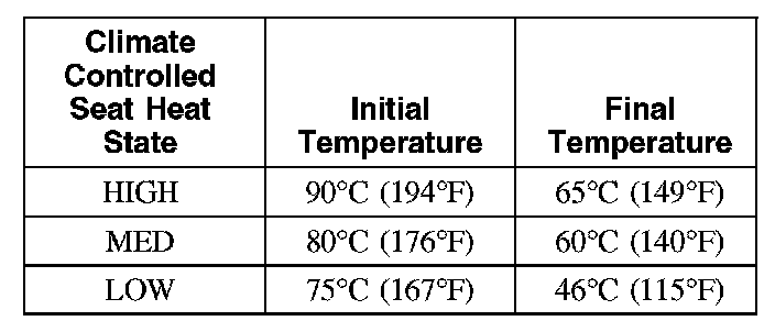
- There are 3 manual settings based on the LEDs above each seat heat switch button on the EATC. The first setting is HIGH (3 LEDs), the second setting is MED (2 LEDs), the third is LOW (1 LED) then OFF (no LEDs).
- In the LOW setting, the climate controlled seat module is set to maintain TED temperature at approximately 46°C (115°F).
- In the HIGH setting, the climate controlled seat module is set to maintain TED temperature at 65°C (149°F).
- If the temperature at one of the TEDs rises above 110°C (230°F) in the HEAT mode or 65°C (149°F) in the COOL mode for more than 4 seconds, the DCSM will record an overtemperature DTC, remove power from the TEDs and go into blower only mode in an attempt to cool down the TEDs. If the TEDs temperature has not dropped to 105°C (221°F) in the HEAT mode or 60°C (140°F) in the cool mode after 30 seconds, the DCSM will shut down and remain off until the ignition is cycled. Also if the DCSM detects an overtemperature twice during the same ignition cycle, it will also shut down.
- When heating, the DCSM will vary the speed of the fans and the TED duty cycle in order to reach and maintain the temperature determined by the switch setting.
- Seat heating has a maximum operating duration of 15 minutes.
Cooling Characteristics

- In cool mode, the TED circuits of a given seat are wired in series internally in the DCSM.
- The climate controlled seat system draws approximately 10 amps for the first 12 minutes and will operate at 2 amps thereafter.
- In cool mode, the TED can remove up to 8°C (14°F) from the ambient air temperature entering the system.
- There are 3 manual settings based on the LEDs above each seat cool switch button on the EATC. The first setting is HIGH (3 LEDs), the second setting is MED (2 LEDs) and the third is LOW (1 LED) then OFF (no LEDs).
- If the temperature at one of the TEDs falls below 5°C (41°F), the climate controlled seat module will shut down the TEDs. If the temperature continues to drop below 2°C (36°F), the climate controlled seat module will shut down the blower motors.
- When cooling, the DCSM maintains constant speed of the fans and constant TED supply voltage (duty cycle) in open loop cool mode.
- Seat cooling has a maximum operating duration of 30 minutes.
The climate controlled seat system is deactivated by one of the following actions:
- Selecting the EATC module setting to manual OFF.
- Turning the vehicle OFF.