Steps 66-131
Engine

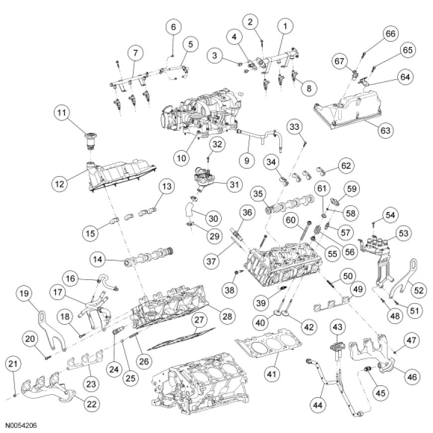
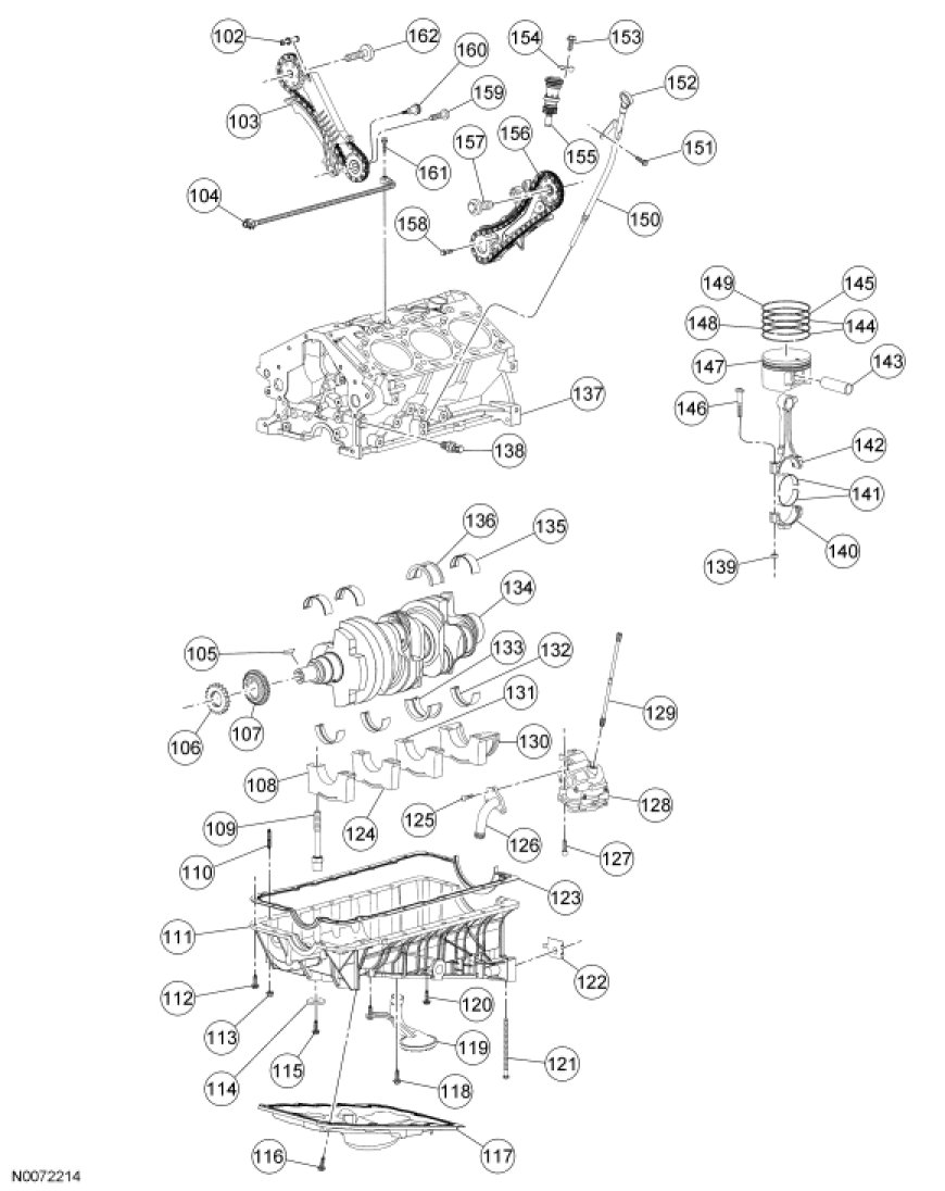
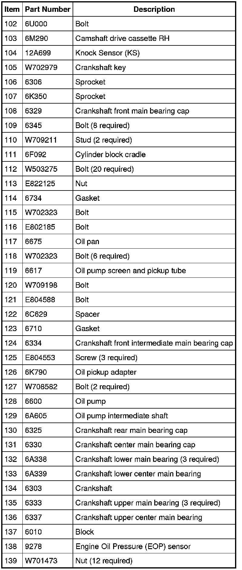
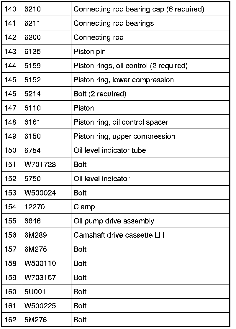
4.0L SOHC Engine - Upper Components
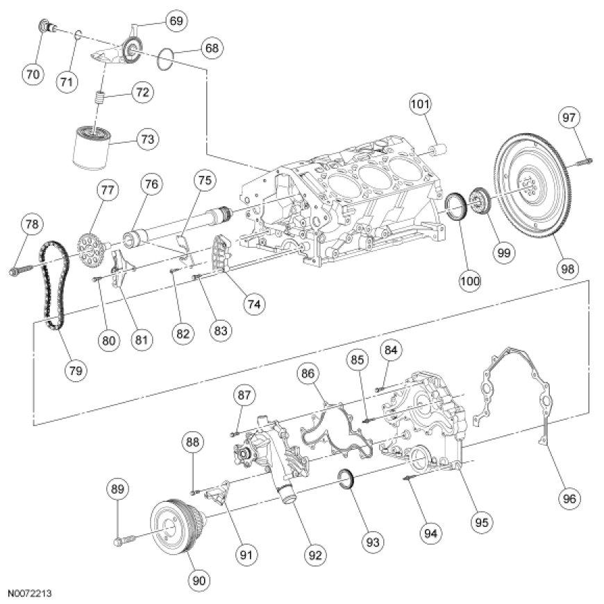
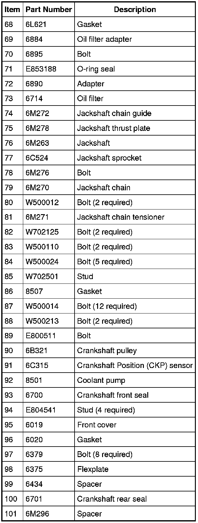
4.0L SOHC Engine - Front and Rear Components
4.0L SOHC Engine - Lower Components
NOTICE: If used as a leverage device, the fuel rail may be damaged. Care must be taken when working around the fuel rail.
NOTE: During engine assembly it may be necessary to check the bearing clearances and crankshaft end play.
NOTE: Before engine assembly, use silicone gasket remover and metal surface prep and a suitable plastic or wooden scraper to clean the sealing surfaces. Follow the directions on the packaging. All sealing surfaces must be clean. Make sure coolant and oil passages are clear.
66. Install the coolant pump pulley and the 4 bolts.
- Tighten to 25 Nm (18 lb-ft).

67. Position the Crankshaft Position (CKP) sensor and install the 2 bolts.
- Tighten to 10 Nm (89 lb-in).

68. NOTE: LH shown, RH similar.
Install the cylinder head gaskets.

69. NOTE: New cylinder head bolts must be installed. They are a torque-to-yield design and cannot be reused.
Install the RH cylinder head. Install 8 new 12-mm bolts and tighten in the sequence shown in 2 stages.
- Stage 1: Tighten to 12 Nm (106 lb-in).
- Stage 2: Tighten to 25 Nm (18 lb-ft).

70. Install 2 new 8-mm bolts.
- Tighten to 32 Nm (24 lb-ft).

71. Tighten the 8 new 12-mm bolts in the sequence shown in 2 stages.
- Stage 1: Rotate 90 degrees.
- Stage 2: Rotate an additional 90 degrees.
72. Position the RH camshaft sprocket.

73. NOTICE: The RH camshaft sprocket bolt is a LH-threaded bolt. Turning the bolt in the wrong direction can damage the bolt.
NOTE: The camshaft sprocket must turn freely on the camshaft. Do not tighten the bolt.
Loosely install the RH camshaft sprocket bolt.

74. Install the RH cassette-to-cylinder head bolt.
- Tighten to 10 Nm (89 lb-in).

75. NOTE: New cylinder head bolts must be installed. They are a torque-to-yield design and cannot be reused.
Install the LH cylinder head and tighten the 8 new 12-mm bolts in the sequence shown in 2 stages.
- Stage 1: Tighten to 12 Nm (106 lb-in).
- Stage 2: Tighten to 25 Nm (18 lb-ft).

76. Install 2 new 8-mm bolts.
- Tighten to 32 Nm (24 lb-ft).
77. Tighten the 8 new 12-mm bolts in the sequence shown in 2 stages.
- Stage 1: Rotate 90 degrees.
- Stage 2: Rotate an additional 90 degrees.
78. Position the LH camshaft sprocket.
79. NOTE: The camshaft sprocket must turn freely on the camshaft. Do not tighten the bolt.
Loosely install the LH camshaft sprocket bolt.

80. Install the LH cassette-to-cylinder head bolt.
- Tighten to 12 Nm (106 lb-in).

81. Turn the crankshaft one revolution clockwise.
82. NOTICE: Do not rotate the engine counterclockwise. Rotating the engine counterclockwise will result in incorrect timing of the engine.
NOTE: The Crankshaft TDC Timing Tool must be installed on the damper and should contact the engine block. This positions the engine at Top Dead Center (TDC).
Install the Crankshaft TDC Timing Tool.

83. NOTE: Camshaft timing slots are off-center.
NOTE: Position the camshaft timing slots below centerline of camshaft.
Install the Camshaft Holding Tool and the Adapter for 303-577 on the front of the RH cylinder head.

84. NOTE: Leave the top 2 Camshaft Sprocket Holding Tool clamp bolts loose.
Install the Camshaft Sprocket Holding Tool and the Adapter for 303-564 on the rear of the RH cylinder head.

85. Install the Timing Chain Tensioner.

86. NOTICE: The RH camshaft sprocket bolt is a LH-threaded bolt. Turning the bolt in the wrong direction can damage the bolt.
Tighten the bolts.
1. Tighten the Camshaft Sprocket Holding Tool top 2 clamp bolts to 10 Nm (89 lb-in).
2. Tighten the camshaft bolt to 85 Nm (63 lb-ft).

87. Install a new washer and the RH timing chain tensioner.
- Tighten to 44 Nm (32 lb-ft).

88. NOTE: Do not tighten the Camshaft Sprocket Holding Tool top 2 clamp bolts. The camshaft sprocket must rotate freely.
Install the Camshaft Sprocket Holding Tool and the Adapter for 303-564 on the front of the LH cylinder head.
89. NOTE: Camshaft timing slots are off-center.
NOTE: Position the camshaft timing slots below centerline of camshaft.
Install the Camshaft Holding Tool and the Adapter for 303-577 on the front of the LH cylinder head.
90. Install the Timing Chain Tensioner.

91. Tighten the bolts.
1. Tighten the Camshaft Sprocket Holding Tool top 2 clamp bolts to 10 Nm (89 lb-in).
2. Tighten the camshaft bolt to 85 Nm (63 lb-ft).
92. Install a new washer and the LH timing chain tensioner.
- Tighten to 44 Nm (32 lb-ft).

93. NOTE: Install the hydraulic lash adjuster in the same positions from which they were removed.
Install the hydraulic lash adjusters.

94. Rotate the crankshaft until the cam lobe on the cylinder being serviced is in the up position.

95. NOTE: Lubricate the parts with clean engine oil.
Using the Valve Spring Compressor, install the roller followers in their original positions.

96. Inspect the RH and LH exhaust manifold gasket mating surfaces for flatness.
97. Install 6 new RH exhaust manifold studs.
- Tighten to 12 Nm (106 lb-in).

98. Install a new gasket, the RH exhaust manifold and the 6 new nuts.
- Tighten to 22 Nm (16 lb-ft).

99. Install 6 new LH exhaust manifold studs.
- Tighten to 12 Nm (106 lb-in).

100. Install a new gasket, the LH exhaust manifold and the 6 new nuts.
- Tighten to 22 Nm (16 lb-ft).

101. NOTE: Prior to installation, use metal surface prep to clean mating surfaces. Follow the directions on the packaging.
Install the Knock Sensor (KS) and the bolt.
- Tighten to 20 Nm (177 lb-in).

102. Install the oil level indicator tube and the bolt.
- Tighten to 10 Nm (89 lb-in).

103. Position the thermostat housing and bypass hose on the coolant pump.
1. Install the 3 bolts.
- Tighten to 11 Nm (97 lb-in).
2. Position the bypass hose clamp.

104. Install the gasket, the RH valve cover and the 6 bolts.
- Tighten to 10 Nm (89 lb-in).

105. Install the gasket, the LH valve cover and the 6 bolts.
- Tighten to 10 Nm (89 lb-in).

106. Install the fuel rail and the fuel injectors as an assembly. Install the 4 fuel rail bolts.
- Tighten to 23 Nm (17 lb-ft).

107. Install the EGR valve tube-to-exhaust manifold.
- Tighten to 34 Nm (25 lb-ft).

108. Position the engine wiring harness.
109. Connect 2 new wiring harness retainers.

110. Connect the Crankshaft Position (CKP) sensor electrical connector.

111. Position the heater tube and bracket, the PCV hose-to-intake manifold fitting and the PCV hose as an assembly and install the rear bolt.
- Tighten to 23 Nm (17 lb-ft).

112. Attach the wiring harness retainer.

113. Connect the coolant hose.

114. Connect the coolant hose.

115. Position the wiring harness bracket and install the bolt.
- Tighten to 28 Nm (21 lb-ft).

116. Connect the KS and the Engine Coolant Temperature (ECT) sensor electrical connectors.

117. Attach the 2 wiring harness retainers to the valve cover studs and connect the 6 fuel injector electrical connectors.

118. Connect the Camshaft Position (CMP) sensor and differential pressure feedback EGR sensor electrical connectors. Attach the wiring harness retainer. Position the electrical connector bracket and install the bolt.
- Tighten to 6 Nm (53 lb-in).

119. Connect the PCV valve hose and electrical connector.

120. Attach the electrical connector. Position the ground wire and install the bolt.
- Tighten to 25 Nm (18 lb-ft).

121. Install the generator bracket.
1. Install the generator bracket and the 3 bolts.
- Tighten to 42 Nm (31 lb-ft).
2. Install the accessory drive belt tensioner and the bolt.
- Tighten to 47 Nm (35 lb-ft).

122. NOTE: The lifting brackets should be installed on the exhaust manifold studs for No. 3 and No. 4 cylinders.
Install the Engine Lifting Brackets.
123. Install the Spreader Bar to the Engine Lifting Brackets.
124. Attach a Heavy Duty Floor Crane to the Spreader Bar and remove the engine from the engine stand.
125. NOTE: The new replacement crankshaft rear seal comes with a speedy sleeve. The speedy sleeve must be installed with the crankshaft rear seal.
NOTE: Be sure the crankshaft rear sealing surface is clean and free of any rust or corrosion. To clean the crankshaft rear sealing surface, use extra-fine emery cloth or extra-fine 0000 steel wool with metal surface prep.
Lubricate the crankshaft rear seal with clean engine oil.
126. Install the Adapter for 303-579 and the Crankshaft Rear Oil Seal Screws.

127. Position the crankshaft rear seal with speedy sleeve on the Adapter for 303-579 and the Crankshaft Rear Oil Seal Screws.

128. Using the Crankshaft Rear Oil Seal Installer, install the crankshaft rear seal with speedy sleeve.

129. Install the crankshaft spacer.
130. Install the crankshaft spacer plate.
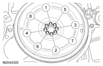
131. NOTE: New flexplate or flywheel bolts must be installed. They are a torque-to-yield design and cannot be reused.
Install the flexplate or flywheel. Tighten the 8 new bolts in 3 stages in the sequence shown.
- Stage 1: Tighten to 13 Nm (115 lb-in).
- Stage 2: Tighten to 50 Nm (37 lb-ft).
- Stage 3: Tighten an additional 90 degrees.