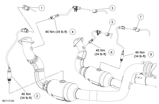
System Diagram
Engine Control Components - Exploded View, 6.2L (2V)


Camshaft Position (CMP) Sensor
NOTE: Intake manifold removed from graphic for clarity.
NOTE: Lubricate the CMP sensor O-ring seal with clean engine oil prior to installation.


Crankshaft Position (CKP) Sensor
NOTICE: The Crankshaft Position (CKP) sensor must be positioned into the fitting on the crankshaft rear seal retainer plate and be flush against the boss on the engine block before the bolt is installed. If the CKP sensor is installed incorrectly, the CKP sensor can be damaged.
NOTE: The intake manifold must be removed to perform this procedure. For additional information, refer to Engine - 6.2L (2V) Service and Repair.
NOTE: After installing the CKP sensor, use the scan tool to perform the Misfire Monitor Neutral Profile Correction procedure, following the on-screen instructions.


Cylinder Head Temperature (CHT) Sensor
NOTE: The intake manifold must be removed to perform this procedure. For additional information, refer to Engine - 6.2L (2V) Service and Repair.


Heated Oxygen Sensor (HO2S) and Catalyst Monitor Sensor (CMS)
NOTE: If necessary, lubricate the Heated Oxygen Sensor (HO2S) and/or Catalyst Monitor Sensor (CMS) with penetrating and lock lubricant to assist in removal.
NOTE: Apply anti-seize to the threads of the HO2S and/or CMS prior to installing.
NOTE: The correct torque wrench setting must be calculated when using the Exhaust Gas Oxygen Sensor Socket to install the HO2S and/or CMS.

Knock Sensor (KS)
NOTE: The intake manifold must be removed to perform this procedure. For additional information, refer to Engine - 6.2L (2V) Service and Repair.


Variable Camshaft Timing (VCT) Variable Force Solenoid
NOTICE: The Variable Camshaft Timing (VCT) variable force solenoid pins must be fully depressed to avoid interference with the VCT valve tips when installing the solenoids. Failure to follow these instructions can result in damage to the engine.
NOTE: The LH or RH valve cover must be removed to perform this procedure. For additional information, refer to Engine - 6.2L (2V) Service and Repair.
NOTE: The bolts are part of the VCT variable force solenoid and cannot be removed.
NOTE: Position the VCT variable force solenoid and tighten the bolts in 2 stages.
- Stage 1: Tighten to 10 Nm (89 lb-in).
- Stage 2: Tighten an additional 45 degrees.


Removal and Installation
1. Refer to the procedures and/or exploded views for any Warnings, Notices, Notes, Materials, Specifications, and Special Tools. Items in the exploded views may not be listed in order of removal.